Light box apparatus for computer editing of photographs

a computer and photograph technology, applied in computing, instruments, projectors, etc., can solve problems such as back and neck strain of computer operators, difficult image comparison, and previous light boxes that have not addressed back and neck strain, and achieve the effect of easing back and neck strain

Inactive Publication Date: 2000-08-08
ROCKWELL RONALD G
View PDF4 Cites 5 Cited by
  • Summary
  • Abstract
  • Description
  • Claims
  • Application Information

AI Technical Summary

Problems solved by technology

Room light flooding onto the image obscures detail and lessens contrast, making image comparison difficult.
Extraneous light emitting from the light box causes glare and produces the same effect.
The constant necessary comparison of the images can cause the computer operator to have back and neck strain.
Previous light boxes have not addressed these problems because the process of scanning photographs and editing the resultant images is a relatively new procedure.

Method used


Image

  • Light box apparatus for computer editing of photographs
  • Light box apparatus for computer editing of photographs
  • Light box apparatus for computer editing of photographs

Examples


Embodiment Construction

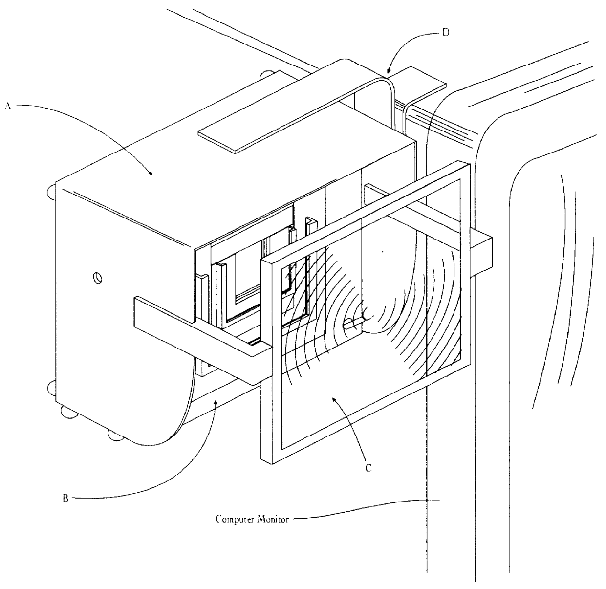
FIG. 1 shows a perspective view of a basic version of the components of my light box attached to a computer monitor. The main parts of the invention consist of Light Box A, Film Matrix B, Magnifying Device C, and Mounting Assembly D.

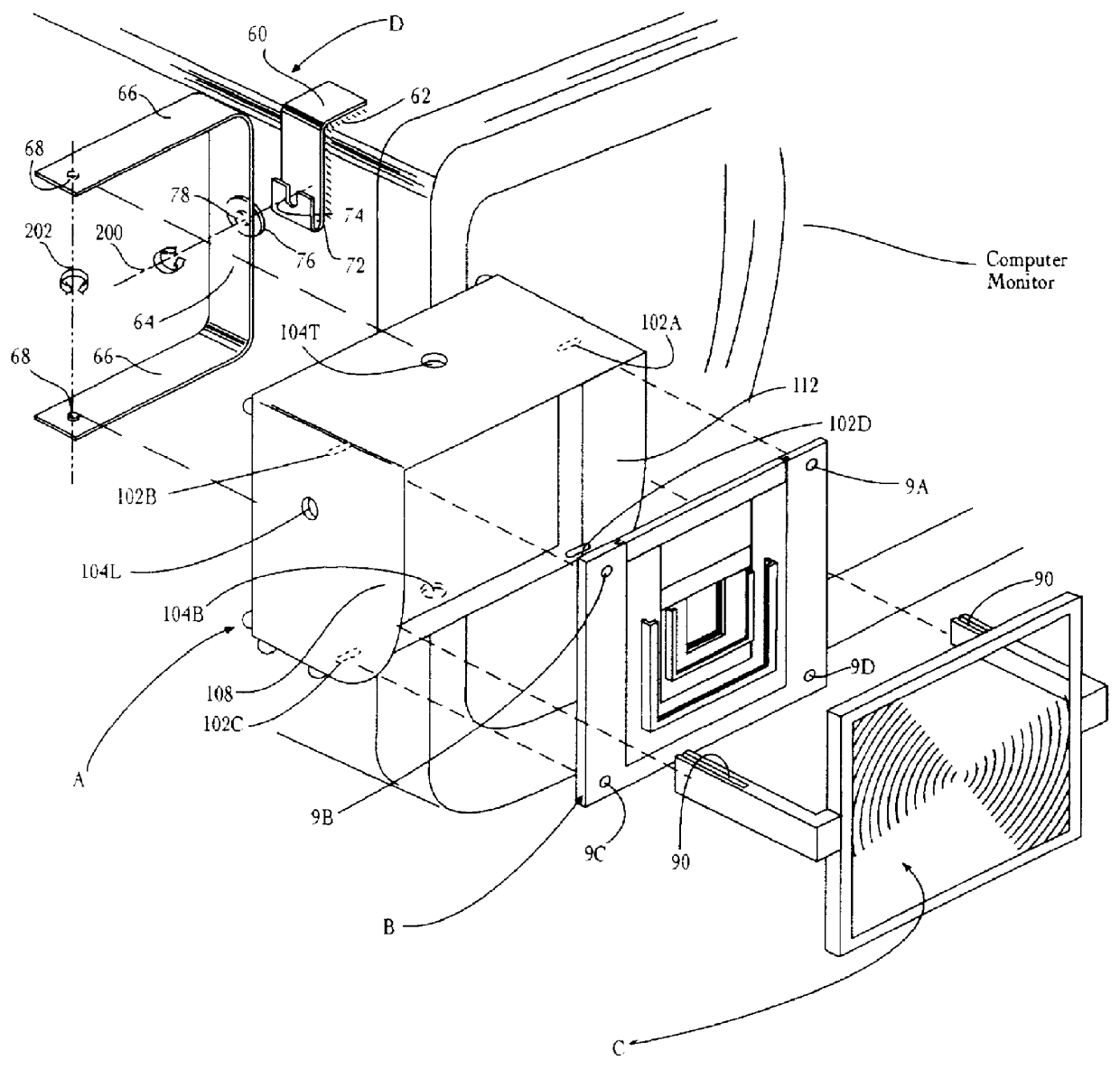
FIG. 1A is an exploded perspective view of the light box components. Computer monitor bracket 60 is connected to the top and side walls of the computer monitor via adhesive-backed hook-and-loop fasteners 62. The lower end of computer monitor bracket 60 is constructed with a bracket channel 72 for the purpose of containing disk 76 on mounting bracket bridge 64 within mounting slot 74 and allowing bridge 64 to rotate in a singular plane on horizontal axis 200 parallel to the screen via axle formed by axle 78 seated in channel 72. U-shaped arms 66 of bridge 64 connect via bracket alignment pins 68 into bracket mounting hole 104T on top and 104B on bottom surface of light box A, allowing rotational movement of light box A on vertical axis 202.

Film matrix ass...


PUM


Abstract

An improved light box and film matrix with magnified viewing means for editing photographic images that have been scanned into a computer for photo manipulation. The light box contains light-blocking shades on top, left and right sides, and may be attached to the side of a computer monitor or placed on a horizontal surface. The film matrix confines photographic film while blocking extraneous light coming from within or behind the light box translucent viewing surface, and may be rotated 900 to accommodate horizontal or vertical images. The matrix holds mounted 35 mm and 6x6 cm slides, and single frames or sheets of 35 mm, 6x6 cm, 6x7 cm, and 9.8x12.4 cm film. A unique mounting bracket allows the light box to be placed vertically, immediately adjacent to the computer screen while comparing images, eliminating eye and back strain associated with conventional horizontally placed light boxes. The bracket can be repositioned on the light box to allow angled placement on a horizontal surface with an adjustable viewing angle. A magnification device is temporarily attached or detached to inspect the photographic image at greater magnification, so that details and color in the photo may be compared to the digital image on the computer.

Description

This invention relates to the graphic arts field and computer editing of photographs, specifically transparencies, slides, or film negatives.DISCUSSION OF PRIOR ARTHistorically, transparent photographic images were placed on a horizontal backlit viewing surface for the purpose of image selection. The photographic image was viewed through a magnifying lens or loupe in order to clearly see details of the image. When an image has been scanned into a computer, it must be edited, and the light box is used in the same manner to compare the photographic image to the computer image. Room light flooding onto the image obscures detail and lessens contrast, making image comparison difficult. Extraneous light emitting from the light box causes glare and produces the same effect. The horizontal orientation of the light box forces the computer operator to lean over the box to view the photo. The constant necessary comparison of the images can cause the computer operator to have back and neck stra...

Claims


Application Information

Patent Timeline
Patent Type & Authority Patents(United States)
IPC IPC(8): G02B25/02G02B27/02G02B25/00G06F1/16
CPCG02B25/005G02B25/02G02B27/024G06F1/1609G06F1/1611
Inventor ROCKWELL, RONALD G.
Owner ROCKWELL RONALD G
Why Eureka
Try Eureka