Minature optical mouse and stylus

a mouse and stylus technology, applied in the field of computer interfaces, can solve the problems of limiting the utility of the cursor control device, affecting the smoothness of the flat surface of the computer, and the inability of computer users to always have convenient access to a smooth flat surface, etc., and achieves the effect of convenient use and efficient combination

Inactive Publication Date: 2006-01-19
SICKLINGER TODD
View PDF13 Cites 114 Cited by
  • Summary
  • Abstract
  • Description
  • Claims
  • Application Information

AI Technical Summary

Problems solved by technology

The prior art cursor control devices each have limitations that limit their utility.
Unfortunately, computer users do not always have convenient access to a smooth flat high friction surfaces, particularly when they are traveling and using a laptop computer or PDA.
Additionally, trackball type mice are susceptible to problems caused by dust and mechanical wear although optical mice work properly on a wide variety of surfaces, as long as the surface has readily detectable surface features, they can be inconvenient to use in many situations.
For example when traveling on a train, a user may not have a convenient place on which to set the mouse down while the user is typing on a keyboard.
Accordingly, it can be quite inefficient to switch back and forth from keyboard to mouse.
Additionally, due to the relatively large size of the light source, prior art optical mice cannot be effectively mounted on a fingertip.
Further, neither trackball type mice nor prior art optical mice work effectively on the viewing surface of a computer monitor.
Finally, the touch pads and pointing sticks provided on laptop computers are difficult to use and they do not provide the same user experience as a mouse.
Some efforts have been made to provide some of theses needs, although none of the previous efforts have been fully successful.
However, operating the disclosed mouse requires the user to move their hand from its normal typing position.
Additionally, the disclosed mouse cannot be used to provide a user experience similar to that of a standard mouse nor can it be used on a computer monitor.
However, the device cannot be used like a standard mouse, since it does not translate motion across an external surface into pointer control signals.
Additionally, it requires a great deal of skill and considerable practice for the user to be able to control a cursor on a video display with any degree of accuracy.
However, the disclosed glove mouse does not adequately simulate traditional mouse operation.
For example, the index finger cannot be used for left mouse button operation, which substantially impedes the ability of some users to perform a “double click” operation.
Additionally, wheel functions such as scrolling are provided by pushing buttons, which does not provide the same intuitive feel as a wheel.
Additionally, the optical motion tracking device is rather bulky and protrudes substantially from the user's fingers, since all of the circuitry, including the light source, associated with the motion tracking device is located on the user's index finger tip.

Method used


Image

  • Minature optical mouse and stylus
  • Minature optical mouse and stylus
  • Minature optical mouse and stylus

Examples


first embodiment

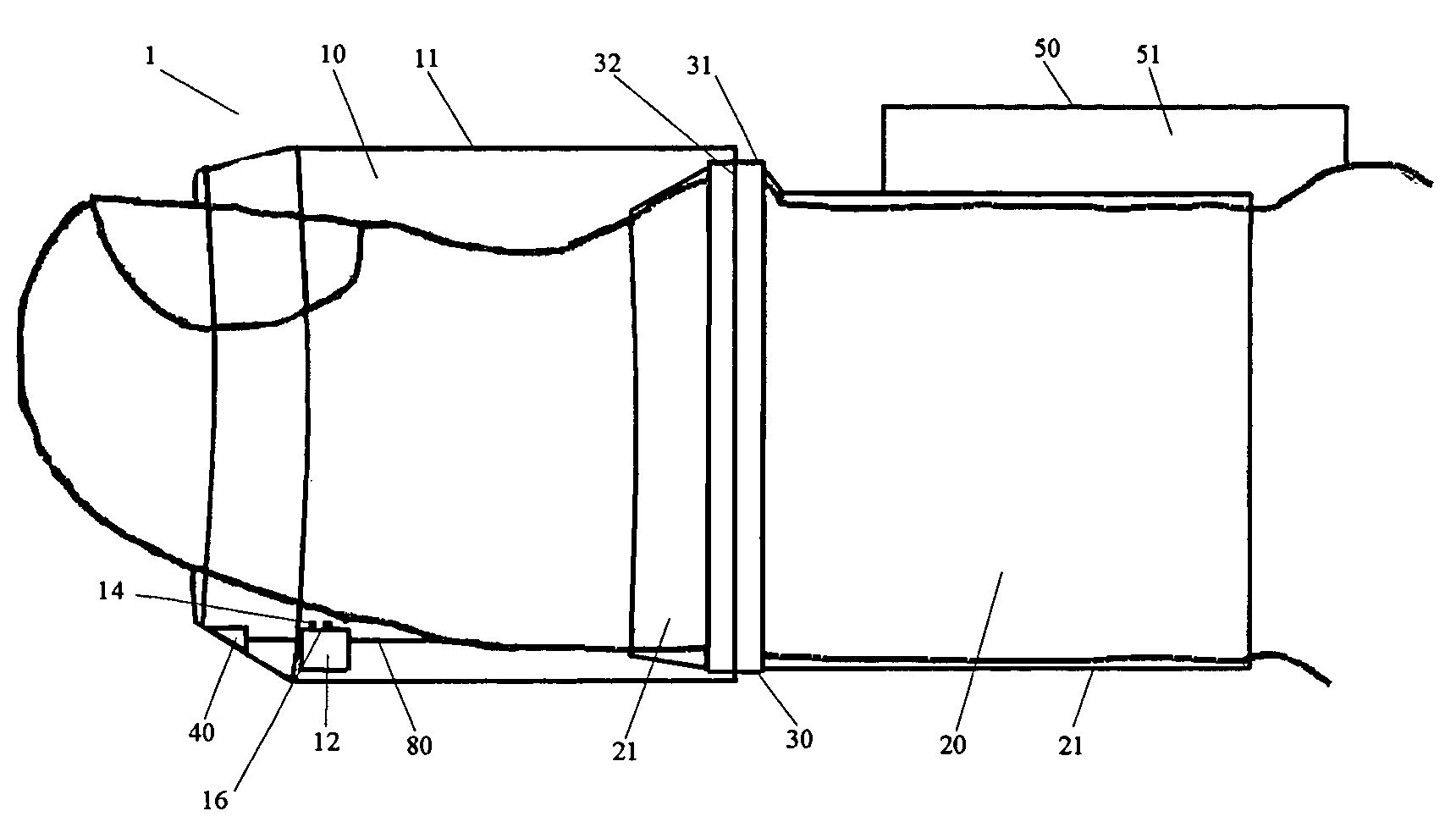
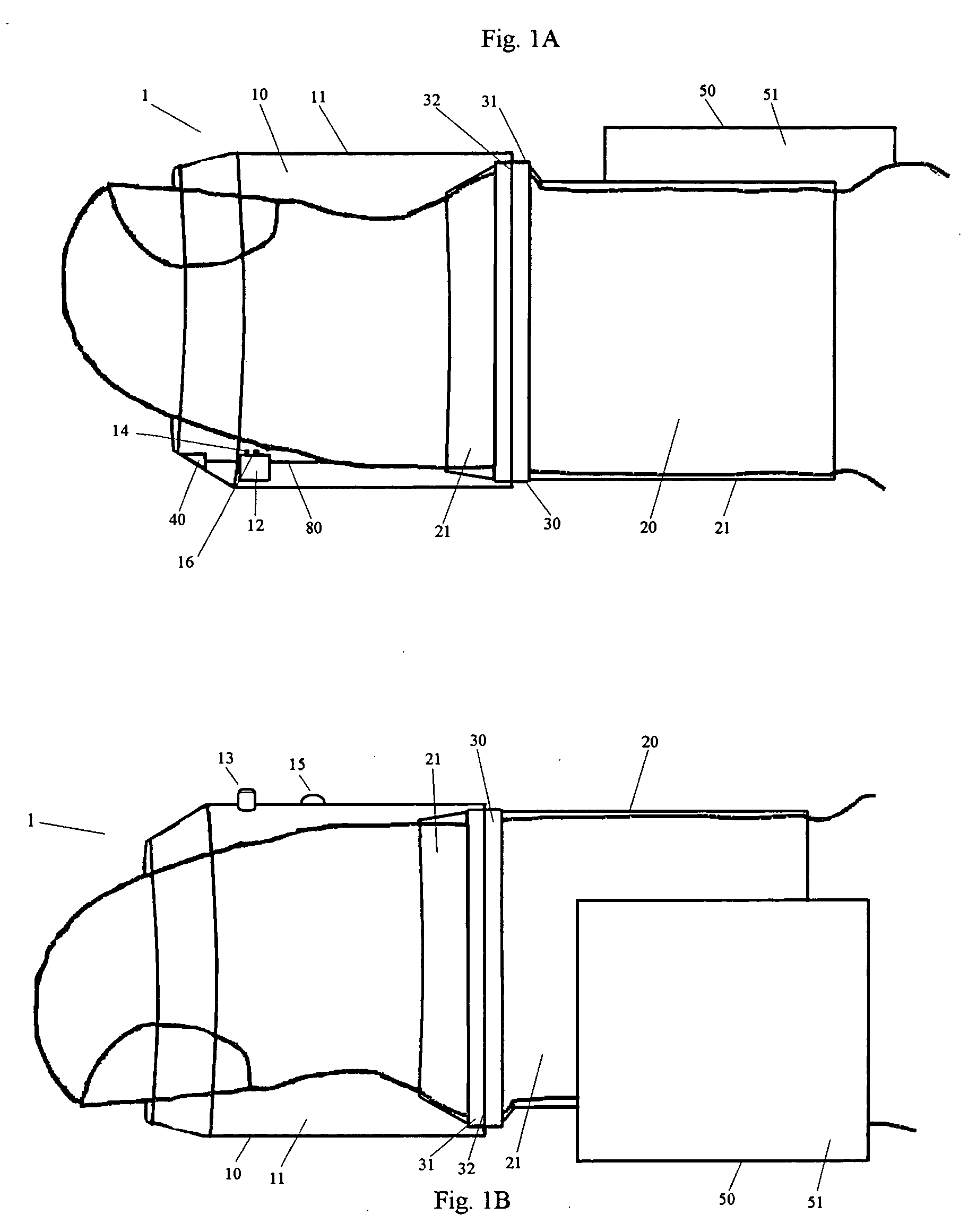
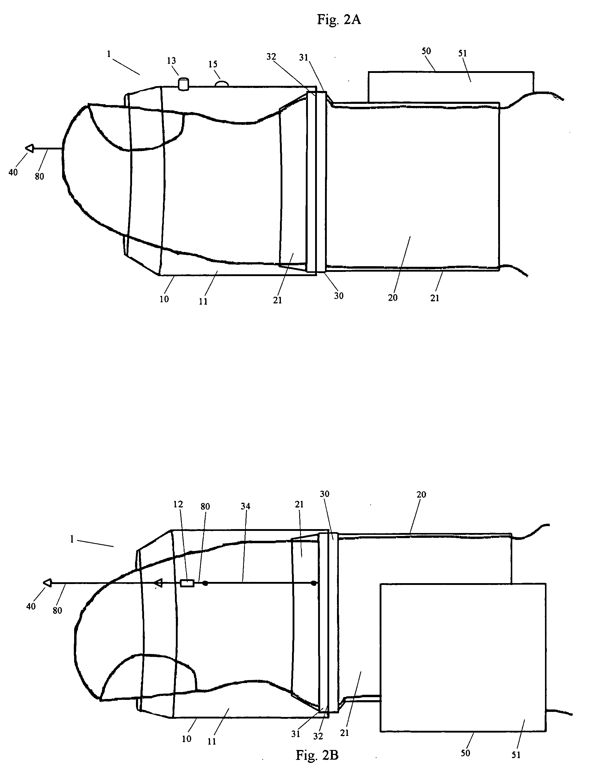
[0026] the present invention is a thumb mounted optical mouse with an included stylus. As shown in FIGS. 1 and 2, thumb mouse 1 is comprised of first mouse section 10, second mouse section 20, bearing 30, optical motion detector 40, remote housing 50, image fiber bundle 60, light source fiber bundle 70, and stylus 80.

[0027] As shown in FIGS. 3A and 3B, first mouse section 10 is comprised of manifold 11, mounting device 12, right mouse button 13, left mouse button 14, wheel 15, wheel button 15a, and pressure sensor 16. Manifold 11 is a hollow substantially rigid cylinder. Mounting device 12 is a rigid bar containing a rectangular opening, which extends through mounting device 12. Mounting device 12 is affixed to the inner surface of manifold 11. Left mouse button 14 and pressure sensor 16 are mounted onto mounting device 12 such that they are positioned between mounting device 12 and a user's thumb. Additionally, first mouse section 10 is configured such that a small space exists bet...

second embodiment

[0048] the present invention is shown in FIGS. 7-9. As shown in FIG. 7, retractable fingertip mouse 100 is comprised of fingertip covering 110, motion detector 120, cable 130, housing 140, and wristband 150. Fingertip covering 110 is made from an elastic flexible cloth like material. Cable 130 passes through fingertip covering 110 and into motion detector 120, which is mounted in fingertip covering 110.

[0049] As shown in FIG. 8, motion detector 120 is comprised of rigid frame 121, pressure sensor 16, left mouse button 14, motion sensor 52, focusing lens 64, and the distal end of light source fiber bundle 70. Cable 130 comprises light source fiber bundle 70 and a protective covering as well as the electrical conductors for pressure sensor 16, left mouse button 14, and motion sensor 52.

[0050] As shown in FIG. 9, housing 140 comprises housing frame 141, spool 142, spring assembly 143, control processor 53, light source 54, gathering lens 55, transmitter 56, power supply 57, and the pr...

third embodiment

[0055] the present invention is shown in FIGS. 10A, 10B, and 11. Glove mouse 200 is comprised of glove body 210, thumb switch 211, ring finger switch 212, pinky switch 213, left motion detector 120a, right motion detector 120b, left cable 130a, right cable 130b, and glove mounted housing 220.

[0056] Left and right motion detectors 120a and 120b are substantially the same as motion detector 120 of the previous embodiment. The components comprising left and right motion detectors 120a and 120b are numbered the same as those for motion detector 120 except that the suffix ‘a’ or ‘b’ is added as appropriate. Additionally, motion detectors 120a or 120b could be provided with a retractable stylus.

[0057] Left cable 130a and right cable 130b are substantially the same as cable 130 from the previous embodiment, except that left cable 130a joins with a wire from thumb switch 211 and right cable 130b joins with wires from ring finger switch 212 and pinky switch 213.

[0058] Glove body 210 is mad...


PUM


Abstract

A small optical mouse that is easy to use, that provides a standard mouse like user experience, that works efficiently in combination with a keyboard, that can be used as a stylus, and that can be used on the viewing surface of a computer monitor as well as related devices and methods.

Description

BACKGROUND OF INVENTION [0001] The disclosed invention is directed to the field of computer interfaces. More specifically, it pertains to devices and methods for the manipulation of a pointer or a cursor that is displayed on a computer monitor or similar device. [0002] A mouse is a well known computer input device. It is used to control the location of a pointer on a video display connected to a computer or other similar device. The pointer location is generally controlled by moving the mouse across a surface such as a mouse pad. The motion of the mouse is translated by electronics and software into the motion of the pointer on the display device. Additionally, a mouse typically has two and sometimes three switches (mouse buttons). These switches are used to activate functions associated with the pointer location. For example, pressing the left mouse button will typically position the cursor to the location of the pointer, and pressing the right mouse button may bring up a list of o...

Claims


Application Information

Patent Timeline
Patent Type & Authority Applications(United States)
IPC IPC(8): G09G5/08
CPCG06F3/014G06F2203/0331G06F3/03545G06F3/0317G06F3/037
Inventor SICKLINGER, TODD
Owner SICKLINGER TODD
Why Eureka
Try Eureka