Microscope condenser with an integrated catch pan

a technology of microscope condensers and catch pans, which is applied in the direction of microscopes, optics, measurement devices, etc., can solve the problems of relatively unproblematic condenser head liquid flowing over the condenser head, and achieve the effect of simple cleaning

Inactive Publication Date: 2000-08-08
LEICA MICROSYSTEMS CMS GMBH
View PDF9 Cites 15 Cited by
  • Summary
  • Abstract
  • Description
  • Claims
  • Application Information

AI Technical Summary

Benefits of technology

What the invention has achieved is that if the glass container breaks, the liquid emerging flows past the mount of the glass container, in the first instance by way of the condenser head, and is then taken up by the catch pan integrated in the microscope condenser. It has proved to be advantageous if a hose connection for draining away the liquid is integrated in the catch pan. `This ensures that even relatively large quantities of running-out nutrient solution can be reliably caught and drained away. The flowing of the liquid over the condenser head is relatively unproblematic, since the housing of said condenser head is constructed in one piece and the front lens is coated and blocked in such a way that no liquid can penetrate there and simple cleaning is possible.

Problems solved by technology

The flowing of the liquid over the condenser head is relatively unproblematic, since the housing of said condenser head is constructed in one piece and the front lens is coated and blocked in such a way that no liquid can penetrate there and simple cleaning is possible.

Method used


Image

  • Microscope condenser with an integrated catch pan
  • Microscope condenser with an integrated catch pan
  • Microscope condenser with an integrated catch pan

Examples


Embodiment Construction

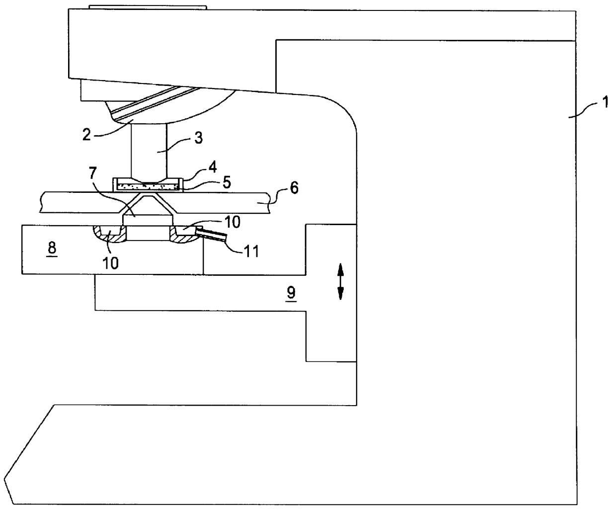
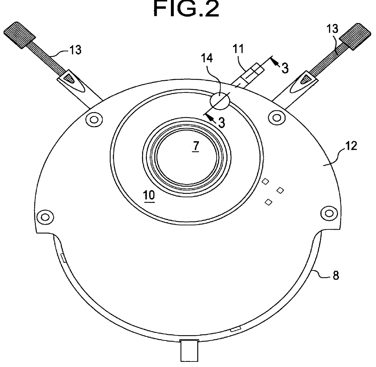
FIG. 1 shows a microscope stand 1 with an objective turret 2 and an objective 3 arranged thereon. The objective 3 projects into a glass container 4 containing a liquid 5 and a sample (not additionally illustrated) . The glass container 4 is held by a specimen holder 6, for example a microscope stage, which is designed in such a way that liquid escaping from the glass container can trickle away below the same through the illumination opening. A microscope condenser 8 with a condenser head 7 [sic] is arranged under the base of the glass container 4. The microscope condenser 8 is arranged on the microscope stand 1 in a manner such that it can be displaced in the direction of the double arrow by means of an adjusting device 9. The microscope condenser 8 has a peripheral depression which is designed as a catch pan 10 and is equipped with a hose connection 11. The depression is dimensioned such that it can hold e.g. the liquid content of the glass container 4 if the hose connection 11 is ...


PUM


Abstract

PCT No. PCT/DE98/02954 Sec. 371 Date Aug. 4, 1999 Sec. 102(e) Date Aug. 4, 1999 PCT Filed Oct. 6, 1998 PCT Pub. No. WO99/22263 PCT Pub. Date May 6, 1999A microscope condenser with a condenser head, with the condenser being fastened to a microscope stand in a manner which allows it to move. A holding device for a glass container filled with a liquid is arranged above the condenser head. A living sample or cell for examination is arranged in the glass container. The microscope condenser in this case has a catch pan for liquid that has overflowed.

Description

The invention relates to a microscope condenser.Known microscopes for examining living samples or cells have a microscope stand with an objective turret and a specimen holder or specimen stage provided below the objective turret. A glass container with a liquid for holding the living preparation is provided on the stage or on the specimen holder. Below this glass container, a microscope condenser is arranged in a manner allowing vertical displacement on the microscope stand.In the case of such IN-VITO or IN-VITRO examinations, the glass container is designed as a petri-dish, bath chamber or perfusion chamber, for example. A temperature-regulated nutrient solution, for example a sugar or salt solution, is used as the liquid in this case. This nutrient solution is continuously exchanged in the glass container via an inlet and outlet. Relatively large quantities of liquid have to be stored as a result of this constant exchange of liquid.During such examinations, moreover, use is made o...

Claims


Application Information

Patent Timeline
Patent Type & Authority Patents(United States)
IPC IPC(8): G02B21/06G02B21/26G02B21/24G02B21/08
CPCG02B21/08G02B21/26
Inventor GAUL, NORBERTWIEBER, KARL
Owner LEICA MICROSYSTEMS CMS GMBH
Why Eureka
Try Eureka