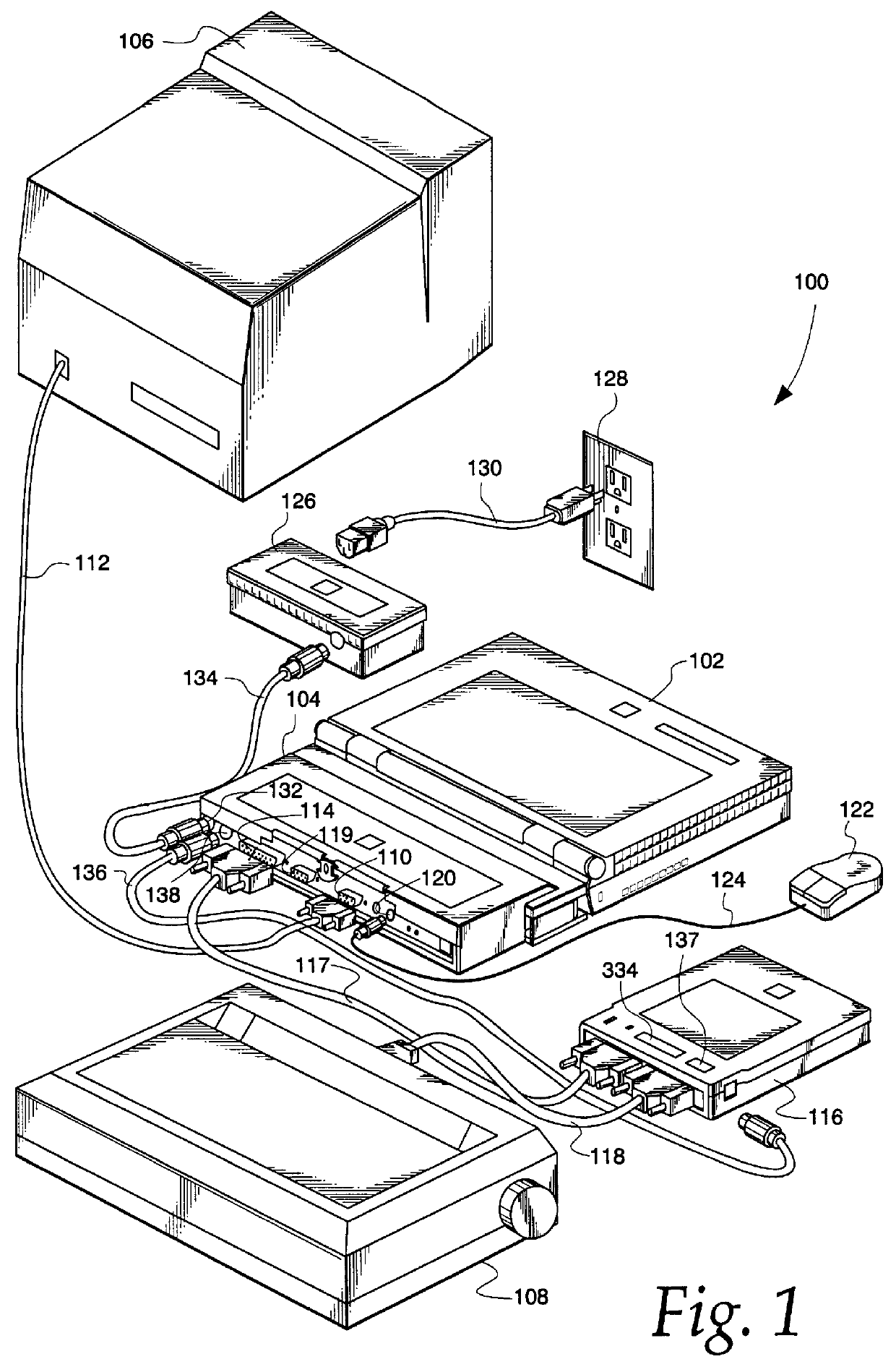
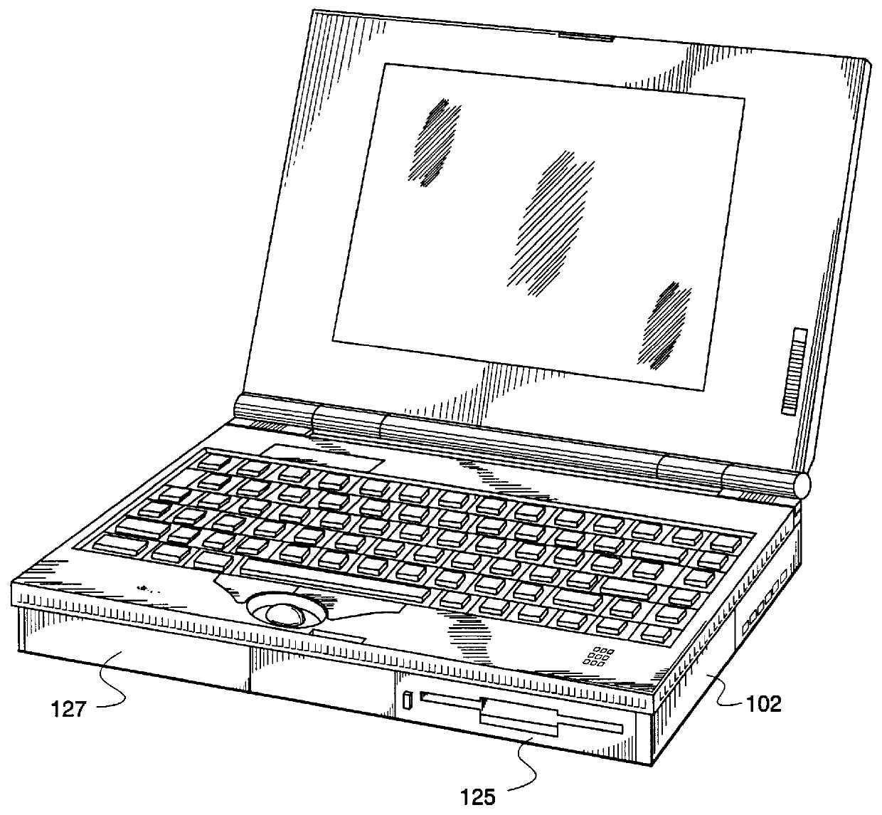
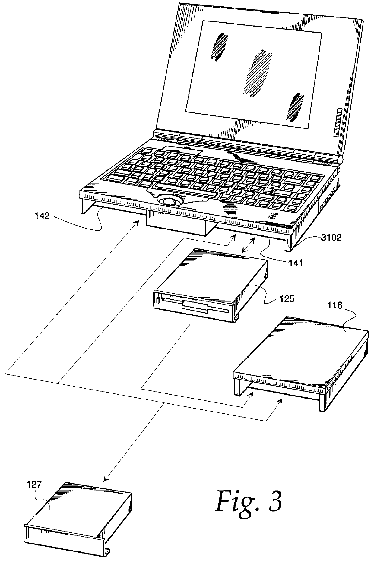
Modular portable personal computer having bays to receive interchangeable modules
- Summary
- Abstract
- Description
- Claims
- Application Information
AI Technical Summary
Benefits of technology
Problems solved by technology
Method used
Image

Examples
Embodiment Construction
1. OVERVIEW
The following describes a control module to be used within ZDS battery packs. This module will allow users to determine the amount of energy left in the battery pack. In addition the module will control charging and charge termination of the battery pack.
Information regarding the present state of the battery pack can be requested by the computer system through a serial interface to the battery pack. This same serial interface will also accept data and software commands from the computer that alter the way the module functions.
Charging of the battery pack will be controlled by the module as well. A signal from the module will control the charging current supplied by the AC Charger / Adapter to charge the battery pack.
These features allow for new battery technologies or charging techniques to be incorporated into existing designs with little or no effect. This separation of function provides for systems which are adaptable between designs of different products and with changi...
PUM
 Abstract
Description
Claims
Application Information
PatSnap Eureka turns technology decisions into work you can execute. Powered by our Innovation Knowledge Graph, it runs expert workflows across engineering, life sciences, materials and intellectual property. Get your review-ready output in minutes.


