Device for stretching thin metal strips by traction

a technology of traction device and metal strip, which is applied in the direction of metal rolling, tensioning/braking arrangement, manufacturing tools, etc., can solve the problems of damage to the planarity of the leveling, the likelihood of the bending of the steel strip to mar the surface, etc., and achieve the effect of high quality

Inactive Publication Date: 2000-08-29
ERWIN KAMPF & MASCHFAB
View PDF10 Cites 24 Cited by
  • Summary
  • Abstract
  • Description
  • Claims
  • Application Information

AI Technical Summary

Benefits of technology

It is an object of the invention to provide a stretch-leveling apparatus that can produces strips of extremely high quality.

Problems solved by technology

Stretch bending is likely to mar the surface from the many contacts with the small rollers that are normally made of steel.
This method is thus disadvantageous when strips with a high surface quality are needed, e.g. for lithographic purposes.
It has been proven that the planarity during leveling is damaged when the transverse shrinkage is impeded by the strip sticking to the retaining rollers.

Method used


Image

  • Device for stretching thin metal strips by traction
  • Device for stretching thin metal strips by traction

Examples


Embodiment Construction

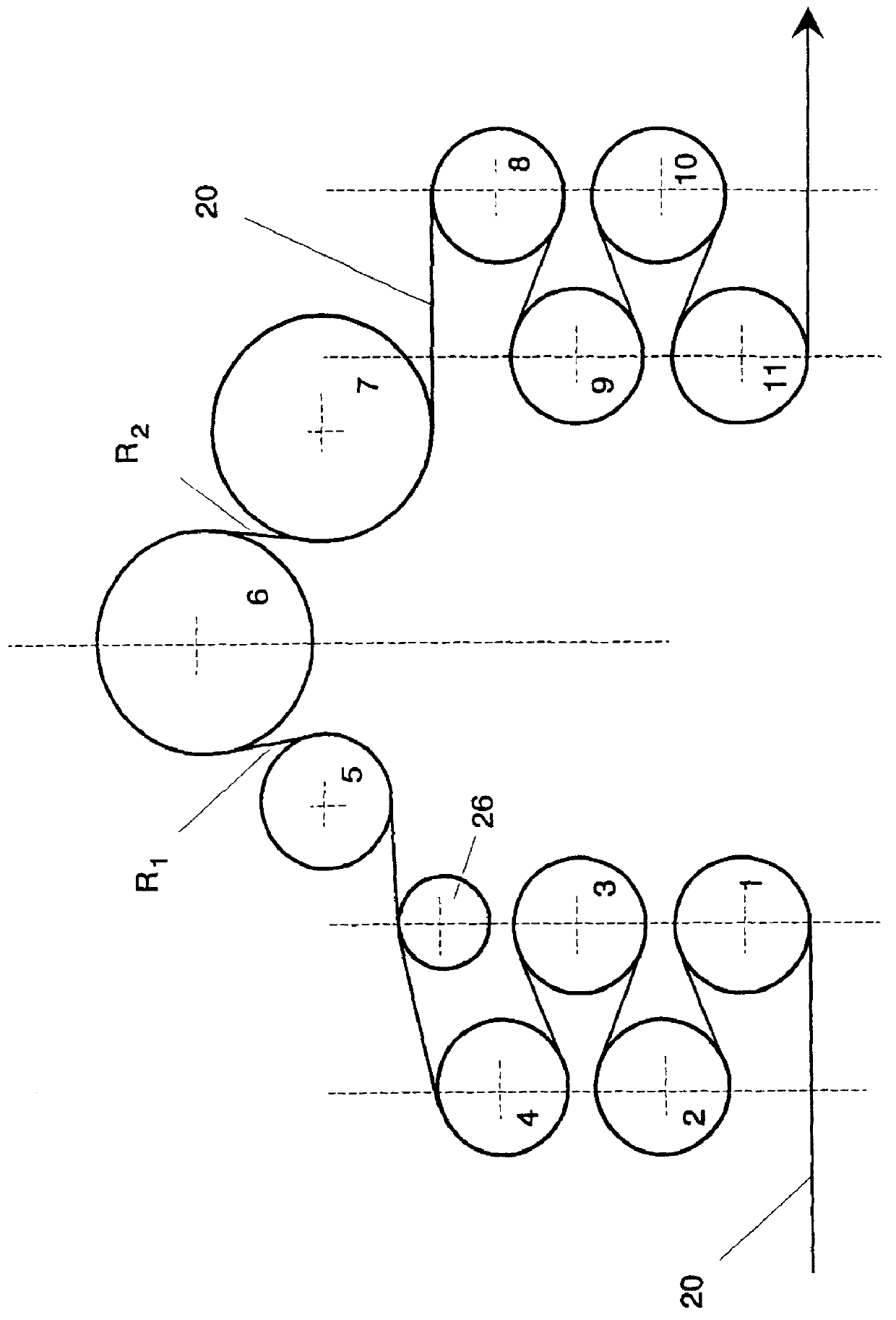
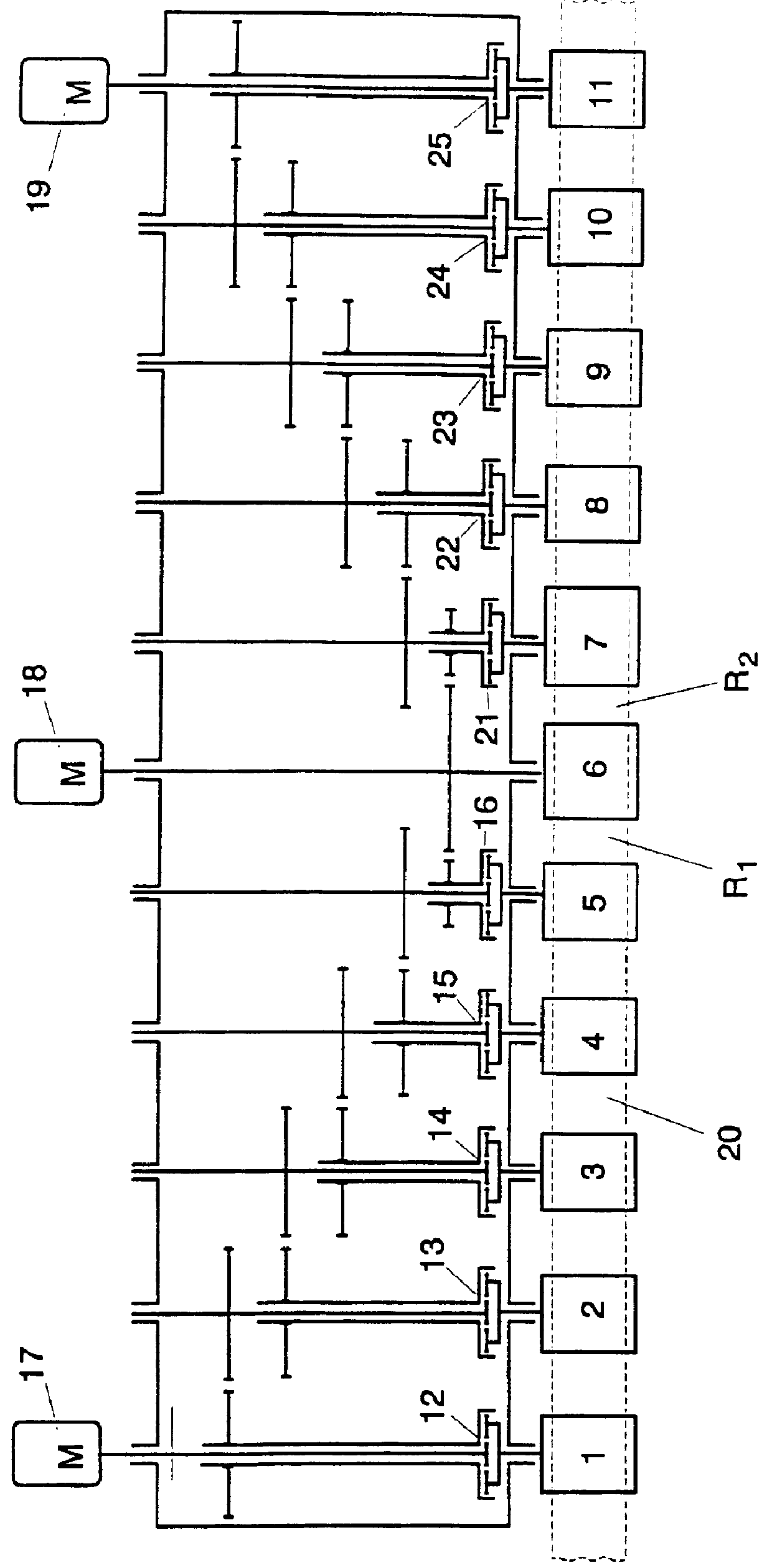
The apparatus serves for stretch leveling thin metal strips, preferably aluminum strips between 0.1 and 0.5 mm thick. It is comprised of a group--here five--of braked rollers 1-5 that are all connected together via differential transmissions 12-16 and controlled jointly with respect to speed. The distribution of the braking torque in the individual rollers 1-5 takes place in the known manner corresponding to the desired force increase between the strip 1 and the individual rollers 1-5 as for example shown in FIG. 2 of German patent 2,529,899. Subsequently there is a central leveling roller 6 that is connected with a drive motor 18. The drive motor 18 is controlled with respect to speed and determines the speed of the leveling apparatus.

Downstream of the central leveling roller 6 is a group of five pulling rollers 7-11 which also are connected together via differential transmissions 21-25 and are controlled jointly with respect to speed. The distribution of the stretching torques tak...


PUM

PropertyMeasurementUnit
thicknessaaaaaaaaaa
thicknessaaaaaaaaaa
thickaaaaaaaaaa

Abstract

PCT No. PCT/EP97/05875 Sec. 371 Date Apr. 27, 1999 Sec. 102(e) Date Apr. 27, 1999 PCT Filed Oct. 24, 1997 PCT Pub. No. WO98/19804 PCT Pub. Date May 14, 1998An apparatus for stretch leveling thin metal strips, in particular aluminum strips between 0.1 and 0.5 mm thick, has a group of braking rollers that are interconnected via differential transmissions and controlled jointly with respect to speed to form a first leveling path with a downstream central speed-controlled leveling roller and that downstream a group of pulling rollers connected together by means of differential transmissions and controlled jointly with respect to speed form a second leveling path with the central leveling roller.

Description

The inventions relates to an apparatus for stretch leveling thin metal strips, in particular aluminum strips having a thickness between 0.1 and 0.5 mm.To continuously level thin metal strips two processes are known: With stretch leveling a free length of the metal strip is tensioned between two roller pairs with a force exceeding its yield limit so as to be plastically lengthened. With stretch bending a strip pretensioned below its yield limit is deflected about rollers of small diameter so that the bending subjects the outer surface to an additional tension. The bending tension combined with the prestress creates a plastic lengthening of the strip that takes place on the upper and lower faces as the strip is looped back and forth.Stretch bending is likely to mar the surface from the many contacts with the small rollers that are normally made of steel. This method is thus disadvantageous when strips with a high surface quality are needed, e.g. for lithographic purposes.German patent...

Claims


Application Information

Patent Timeline
Patent Type & Authority Patents(United States)
IPC IPC(8): B21D1/00B21D1/05
CPCB21D1/05
Inventor HUTZENLAUB, ARMINHEISTER, PAULUS
Owner ERWIN KAMPF & MASCHFAB
Why Eureka
Try Eureka