Flow control apparatus

a flow control and flow control technology, applied in the direction of functional valve types, process and machine control, instruments, etc., can solve the problems of serious burns and danger for small children

Inactive Publication Date: 2000-08-29
AL HAMLAN SALEH A
View PDF6 Cites 25 Cited by
  • Summary
  • Abstract
  • Description
  • Claims
  • Application Information

AI Technical Summary

Problems solved by technology

(about 70.degree. C.) which can cause serious burn

Method used


Image

  • Flow control apparatus
  • Flow control apparatus
  • Flow control apparatus

Examples


Embodiment Construction

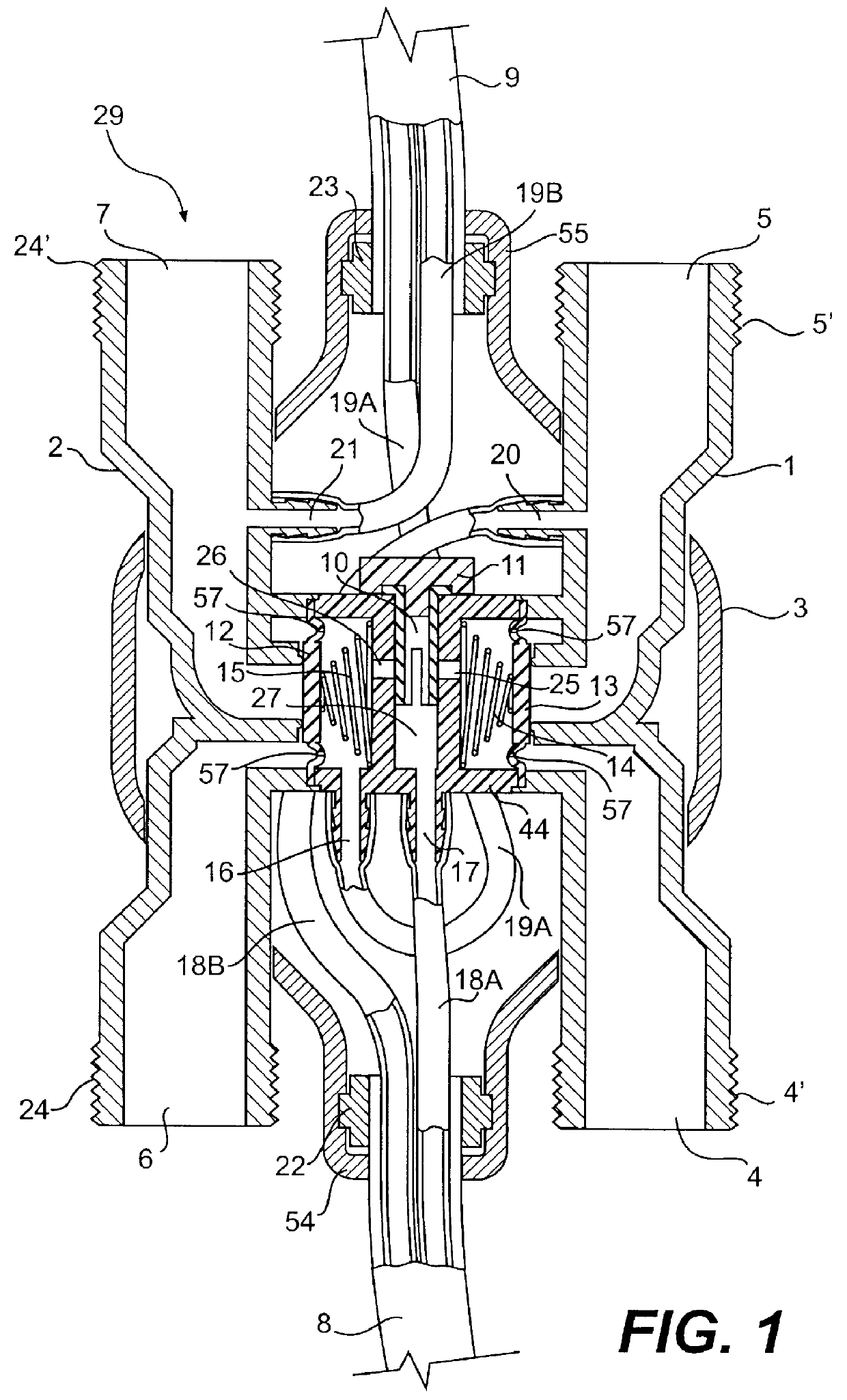
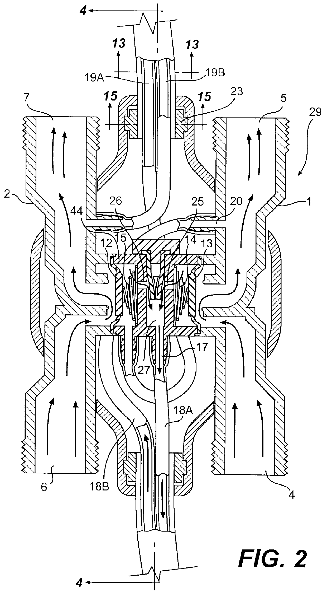
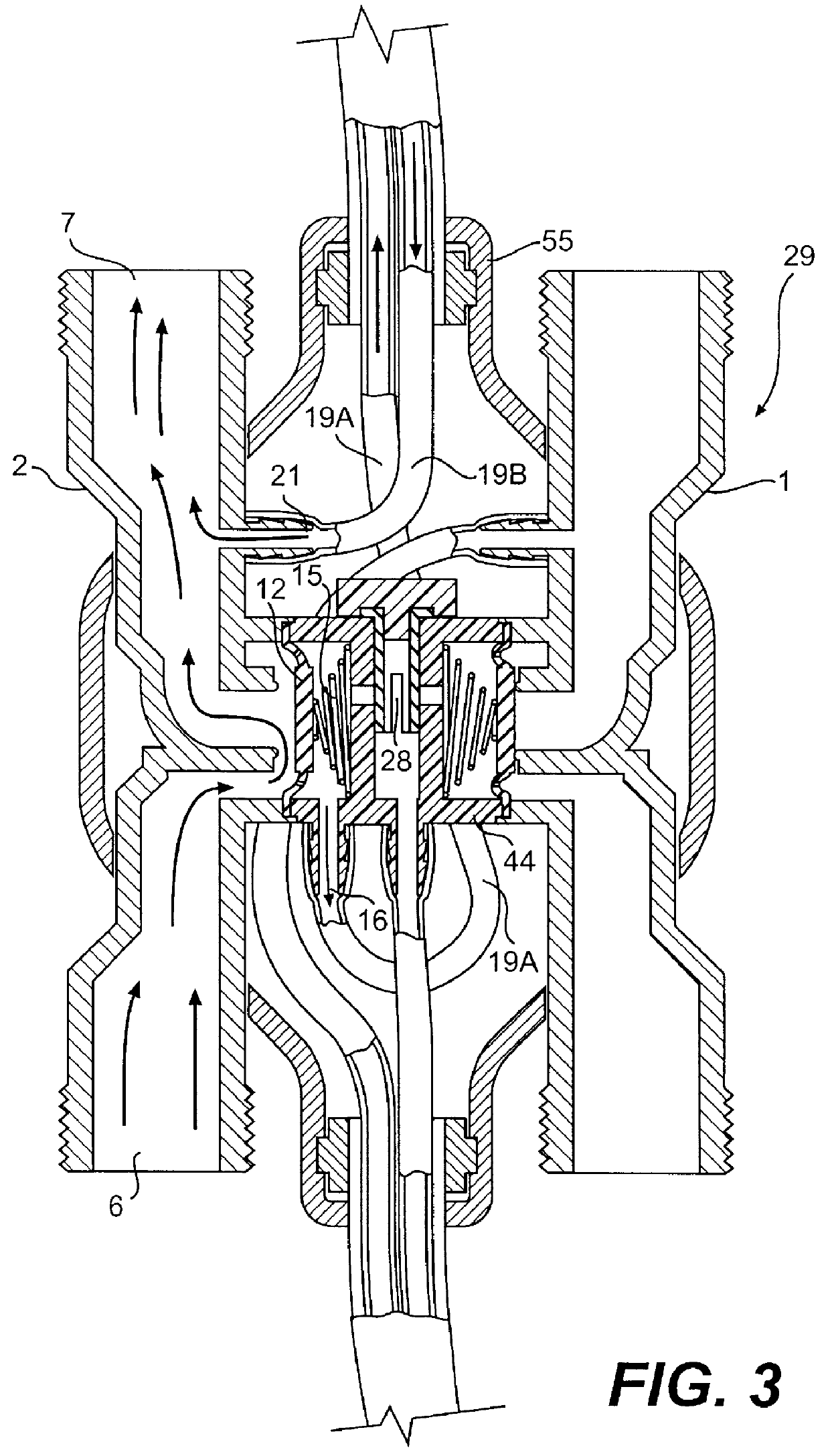
As shown more clearly in FIGS. 1-3, a mixing valve 29 includes an inlet or fluid conduit 4 including a threaded portion 4' for connecting the mixing valve to a source of cold water (not shown). The valve 29 also includes a second fluid conduit 5 with a threaded end portion (5') for connection to a common outlet 60 (shown in FIG. 22). The fluid conduits 4 and 5 are defined by an outer wall 1. Third and fourth fluid conduits 6 and 7 are defined by an outer wall 2 and adapted to be connected to a source of hot water and the common outlet by means of threaded end portions 24 and 24'.

A pair of diaphragm valves 12 and 13 are disposed within chamber (12') and (13') which are defined by walls 44 and 44' and biased in a closed position (FIG. 1) by springs 14 and 15. The diaphragm valves 12 and 13 which are disposed within a housing 3 separate the first and second fluid conduits 4 and 5 and third and fourth conduits 6 and 7 respectively. The mixing valve 29 also includes a third fluid chamber...


PUM


Abstract

A flow control apparatus for regulating the flow of hot and cold water through a mixing valve and for preventing undiluted hot water from being inadvertently delivered to a common outlet includes a common chamber and a pair of diaphragm valves on opposite sides of the common chamber. It also includes a check valve in the common chamber for opening and closing the diaphragm valves. Conventional piping, preferably flexible piping is used to connect the mixing valve to a source of hot water and to a source of cold water. The diaphragm valves and check valve are connected and arranged to prevent the flow of hot water through the mixing valve in the absence of a flow of cold water. The flow control apparatus may also include a mechanism for overriding the mixing valve in order to deliver an undiluted flow of hot water to the common outlet.

Description

This invention relates to a flow control apparatus and system for regulating the flow of two liquids and more particularly to a flow control apparatus and system for regulating the flow of hot and cold water through a mixing valve and for preventing undiluted hot water from passing through the valve.BACKGROUND FOR THE INVENTIONSystems and apparatus for regulating the flow of one liquid in response to the flow of another are well known. For example, a U.S. Pat. No. 2,581,855 of Griffith discloses a system for controlling the temperature in a shower or the like. In that system, cross controls are provided so that compensation is made for a sudden or even a gradual change in the pressure in one or more of the water sources without a change in the relative flow of the other.Another approach to flow control apparatus is disclosed in the U.S. Pat. No. 2,479,177 of Miller. The Miller patent discloses a duplex diaphragm valve for use in a commercial washing machine. As disclosed therein, a ...

Claims


Application Information

Patent Timeline
IPC IPC(8): G05D23/13G05D23/01
CPCG05D23/1313Y10T137/2496Y10T137/2572
Inventor AL-HAMLAN, SALEH A.
Owner AL HAMLAN SALEH A
Why Eureka
Try Eureka