Aseptic or sanitary diaphragm valve

a diaphragm valve and sanitary technology, applied in the direction of diaphragm valves, valve details, valve arrangements, etc., can solve the problems of significant capital expense, complex and difficult to repair and maintain sanitary valves used in dairy industries, food processing industries, etc., and achieve simple and reliable construction. , the effect of simple structur

Inactive Publication Date: 2014-08-19
FELDMEIER EQUIP
View PDF11 Cites 0 Cited by
  • Summary
  • Abstract
  • Description
  • Claims
  • Application Information

AI Technical Summary

Benefits of technology

[0004]It is an object of the present invention to provide an aseptic or sanitary diaphragm valve arrangement of simple construction, capable of being cleaned in place when installed in conduits for liquid food products, pharmaceuticals, beauty care products, or any other product which must be processed under sanitary conditions. The diaphragm valve must be capable of controlling flow and / or pressure of the liquid product, but should also be of simple, reliable, and sturdy construction so as to avoid the drawbacks of the prior art.
[0005]It is another object to provide an aseptic or sanitary valve that is employs a floating valve plug contained within a cylindrical valve body, and which avoids any need to machine or manufacture complex surfaces within the valve cavity.
[0007]It is a further object to provide a diaphragm valve that is capable of reliably opening and closing to regulate the flow of fluids in the sanitary flow path.
[0013]In a favorable embodiment, the foot portion of the valve plug has a domed bottom surface that rests on said diaphragm. This facilitates the flow of the C.I.P. cleaning fluid over these surfaces during a cleaning operation.

Problems solved by technology

No threaded connectors can be used anywhere that the liquid product flows, because of the difficulty in cleaning the threads.
In order to accommodate this requirement, the sanitary valves used in the dairy industry, food processing industries, pharmaceutical industry, have been complex and difficult to repair and maintain, and represent a significant capital expense.

Method used


Image

  • Aseptic or sanitary diaphragm valve
  • Aseptic or sanitary diaphragm valve
  • Aseptic or sanitary diaphragm valve

Examples


Embodiment Construction

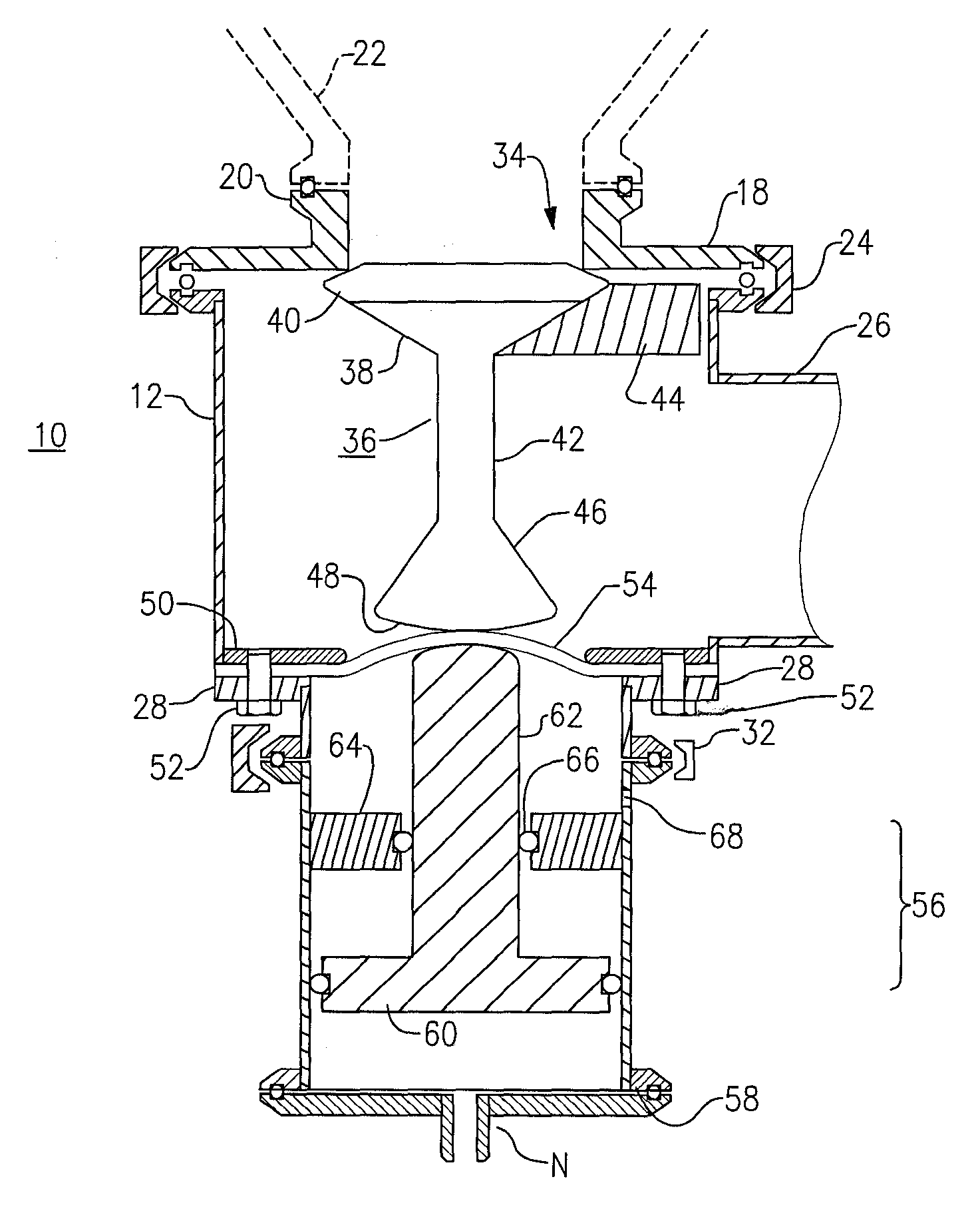
[0025]With initial reference to the embodiment illustrated in FIGS. 1 to 3, an aseptic valve or sanitary valve 10 of the present invention may be employed on a sanitary conduit, or may be employed at a lower drain of a sanitary tank or vessel, adapted for a dairy product, another edible product such as fruit juice, sauce or soup, or a pharmaceutical product for human or veterinary use, or a cosmetic, beauty-related, or dermatological creme or liquid.

[0026]The aseptic or sanitary valve 10 of this embodiment has one inlet and one outlet, and may be employed at the drain or outlet of a vertical tank. Other embodiments of this valve may have two or more controlled outlets.

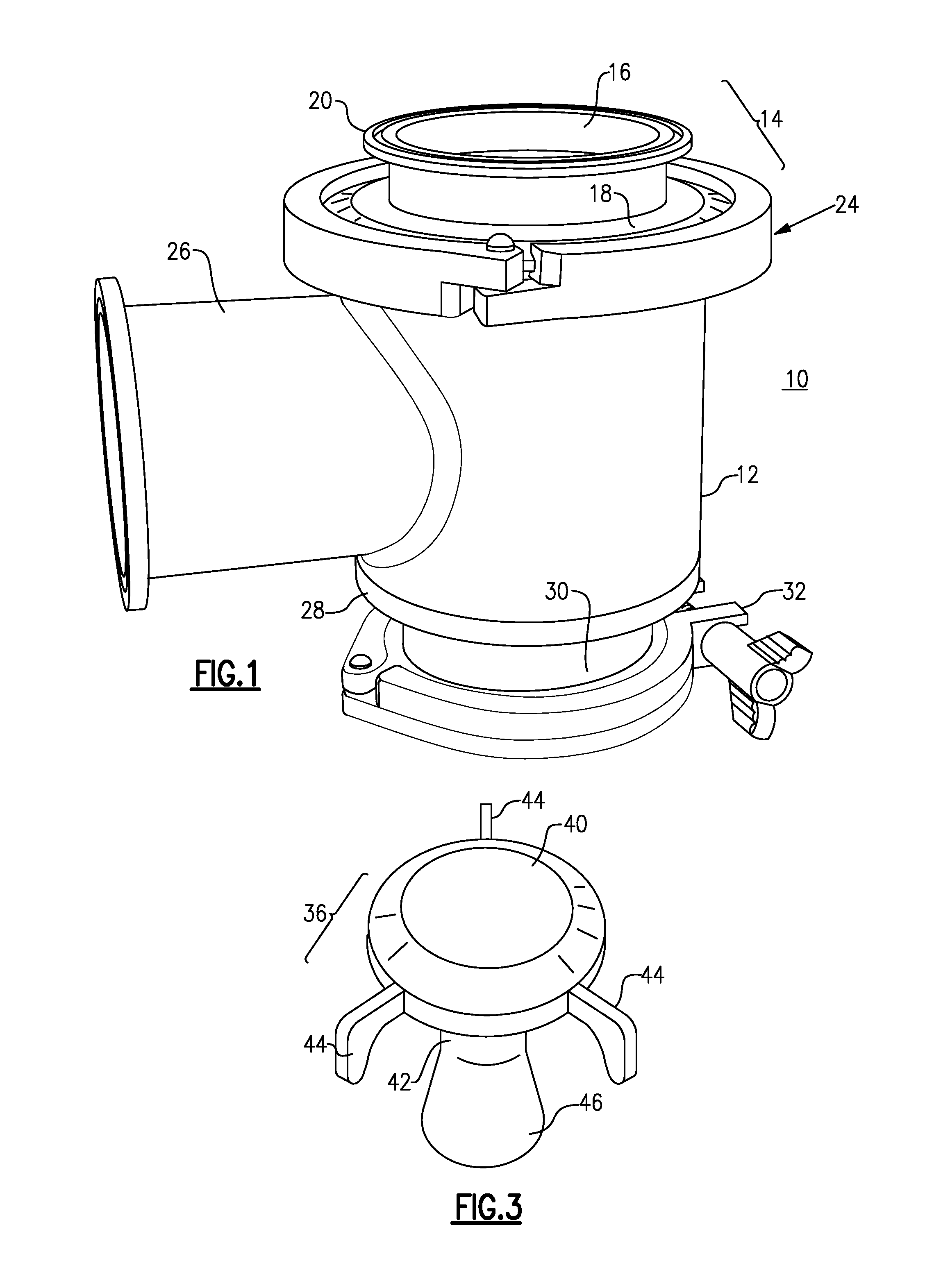
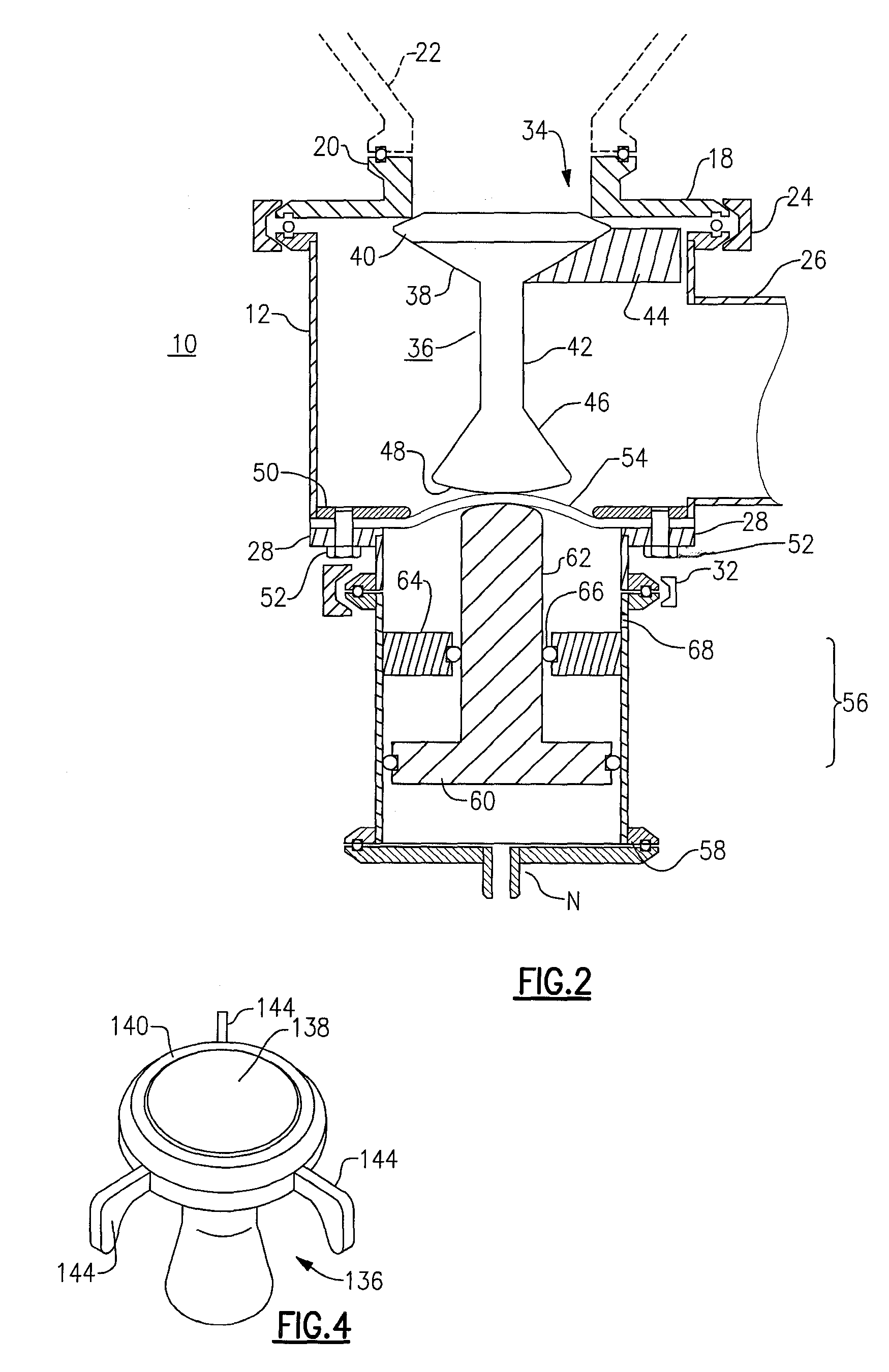
[0027]In the sanitary diaphragm valve 10 of this embodiment, a cylindrical valve housing 12 is formed of a cylindrical wall that defines a hollow valve space within it. An upper valve portion 14 is affixed onto the upper end of the housing 12 and includes an inlet tube 16 and a top plate 18 that has a center opening. I...


PUM


Abstract

An aseptic valve or sanitary valve employs a floating plug situated within a cylindrical valve housing. The floating valve plug has a head that seats against an inlet opening, and has a stem and a generally conic foot that rests upon a diaphragm formed of a flexible, food-grade membrane. An actuator below the diaphragm urges the plug up to lodge against the inlet opening, and relieves force on the membrane and plug to open the valve. Spacer arms radiate from the stem or head of the plug, to keep the plug centered in the housing.

Description

[0001]This is a continuation-in-part of and commonly-assigned U.S. patent application Ser. No. 12 / 883,518, filed Sep. 16, 2010, which is a continuation-in-part of application Ser. No. 12 / 766,009, filed Apr. 23, 2010, now abandoned.BACKGROUND OF THE INVENTION[0002]This invention relates to equipment for processing of liquids that must be kept aseptic, i.e., pharmaceuticals, dairy products, other food products for human consumption, beauty products, skin care products, and the like. The invention is more particularly concerned with sanitary valves of the type used in the dairy, food processing, and / or pharmaceutical industries, in which the flow of a fluid is to be regulated or diverted from one flow path to another. The invention is more directly concerned with diaphragm valves, that is, valves of the type in which a flexible membrane isolates the mechanical portions of the valve from the flow of fluid. The invention is more specifically concerned with a diaphragm valve of simple des...

Claims


Application Information

Patent Timeline
Patent Type & Authority Patents(United States)
IPC IPC(8): F16K31/122F16K31/22
CPCF16K7/16F16K31/122F16K41/12
Inventor FELDMEIER, ROBERT, H
Owner FELDMEIER EQUIP
Why Eureka
Try Eureka