Impact absorber

a technology of impact absorber and shock absorber, which is applied in the direction of vibration dampers, mechanical devices, bumpers, etc., can solve the problem of large installation spa

Inactive Publication Date: 2000-08-29
MANNESMANN BOGE
View PDF11 Cites 42 Cited by
  • Summary
  • Abstract
  • Description
  • Claims
  • Application Information

AI Technical Summary

Problems solved by technology

This prior art design involves a high level of construction outlay and requires a large installation space.

Method used


Image

  • Impact absorber

Examples


Embodiment Construction

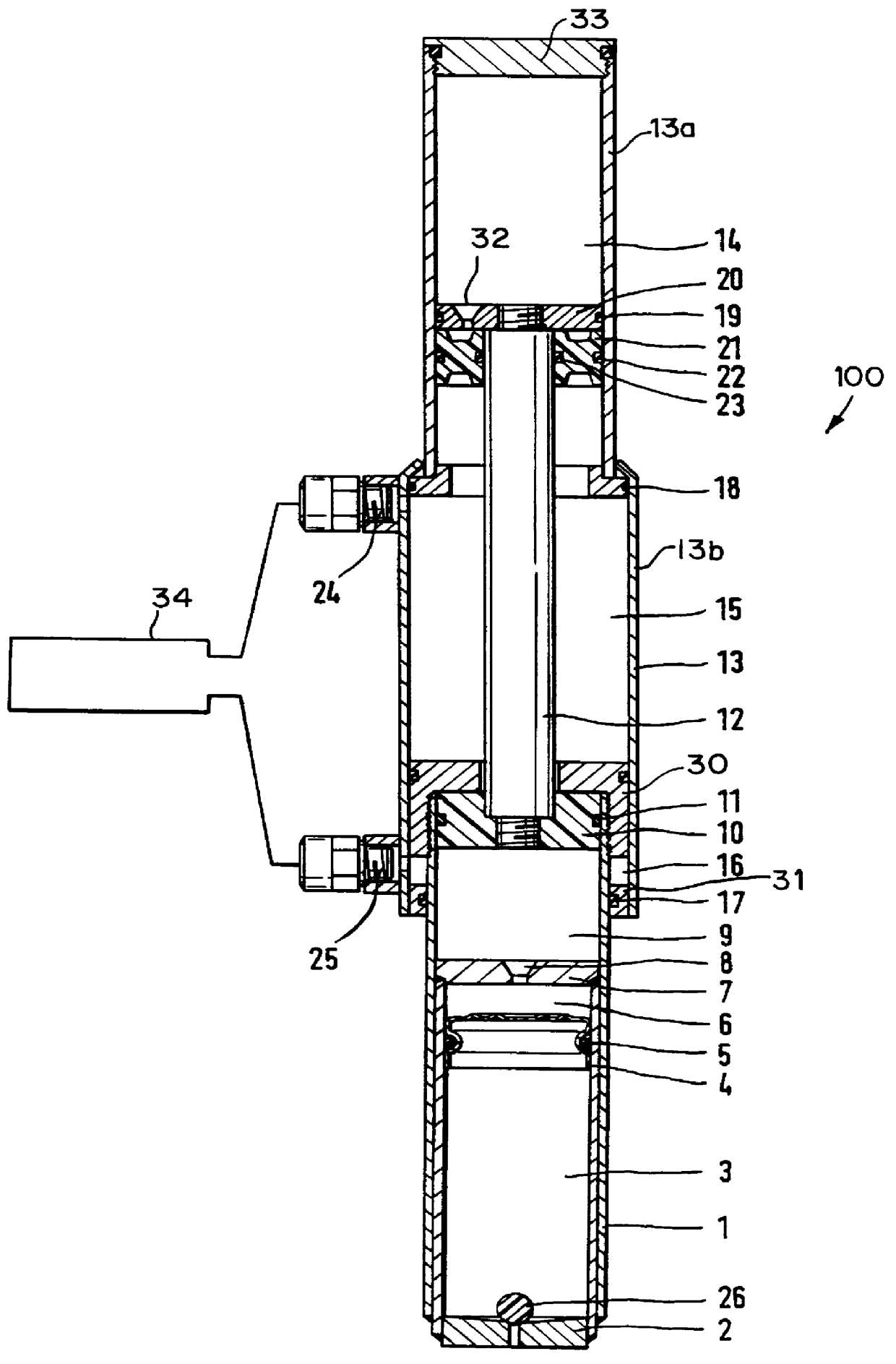
The FIGURE shows a longitudinal section of an impact absorber 100 having a variable length. An internal tube 1 is closed off to the outside by a base 2 and accommodates a gas space 3 provided with a gas filling subjected to high pressure. The internal tube 1 also includes a first liquid space 6 separated from the gas space 3 by a separating piston 4 which slides axially within the internal tube and is sealed on the inside wall of the internal tube by a sealing ring 5. The other end of the first liquid space 6 is bounded by an intermediate wall 7 which is attached inside the internal tube 1. The intermediate wall 7 has a throttle opening 8 and thus produces a hydraulic connection to a second liquid space 9 which is also arranged in the internal tube 1. On the other side of the second liquid space 9, a working piston 10 acts on the second liquid space 9. The working piston 10 is sealed off in the internal cylinder 1 by a sealing ring 11. The working piston 10 is prevented from leaving...


PUM


Abstract

An impact absorber for decelerating a vehicle during a collision with an obstacle by hydraulic damping forces and pneumatic spring forces includes two tubes that are telescopically displaceable one inside the other. An internal tube of the two tubes is closed off to the outside by a base. A gas space subjected to high pressure is disposed adjacent said base and interacts with a first liquid space via a separating piston which is axially guided in the internal tube in a sealed manner. The first liquid space is hydraulically connected to a second liquid space via a throttle opening through an intermediate wall attached inside the internal tube. A working piston attached to a piston rod is guided in the internal tube in a sealing manner and interacts via the piston rod with a third liquid space in an external one of the two tubes. A control which can be connected to two chambers is provided to extend the impact absorber or to return it to a normal position.

Description

1. Field of the InventionThe present invention relates to an impact absorber for decelerating a vehicle during a collision with an obstacle by hydraulic damping forces and pneumatic spring forces. The impact absorber has an internal tube and an external tube that are telescopically displaceable one inside the other. The internal tube is closed off to the outside by a base and has a gas space which is subjected to high pressure and interacts with a first liquid space by a separating piston which is axially guided in the internal tube in a sealed off manner. The first liquid space is hydraulically connected via a throttle opening, which is located in an intermediate wall attached inside the internal tube, to a second liquid space bounded by a working piston. The working piston is attached to a piston rod and is guided in the internal tube in a sealing manner and interacts with a third liquid space. A control which can be connected to two chambers is provided to extend the impact absor...

Claims


Application Information

Patent Timeline
Patent Type & Authority Patents(United States)
IPC IPC(8): B60R19/40B60R19/24F16F9/16F16F9/00F16F9/06F16F9/14B60R19/32
CPCB60R19/40F16F9/06F16F9/067F16F9/16B60R19/32
Inventor AYYILDIZ, METINKIRCHNER, HOLGER
Owner MANNESMANN BOGE
Why Eureka
Try Eureka