Shock absorbing vehicle body structure

a vehicle body and shock absorption technology, applied in the direction of vehicular safety arrangments, pedestrian/occupant safety arrangements, jet propulsion mountings, etc., can solve the problems of increased vehicle deceleration and sudden decrease of vehicle deceleration

Inactive Publication Date: 2000-08-29
HONDA MOTOR CO LTD
View PDF15 Cites 94 Cited by
  • Summary
  • Abstract
  • Description
  • Claims
  • Application Information

AI Technical Summary

Benefits of technology

With the above arrangement, the front subsidiary frame receiving the load due to the full-lap collision of the vehicle is retreated relative to the main frame, and a peak value of the deceleration is produced in a moment of separation of rear ends of the subsidiary frame from the main frames. However, in this operation, because the left and right rear ends of the front subsidiary frame are respectively separated from the main frames with the time lag therebetween, two dispersed peak values of the deceleration are provided. As a result, the peak values can be suppressed to lower values to reduce the shock associated therewith, and the deceleration can be continuously produced, as compared with a case where the left and right rear ends of the front subsidiary frame are separated simultaneously from the main frames to produce a single peak value.
With the above feature, if the step(s) are provided in the side members, the rigidity is decreased and therefore, the difference in rigidity between the left and right side members can be easily achieved by providing the difference(s) in number and / or shape of the step(s).
With the above feature, if only one of the side members is reinforced with the reinforcing member, its rigidity is increased. Therefore, the difference in rigidity can be provided between the left and right side members by reinforcing the one side member with the reinforcing member.

Problems solved by technology

When the front subsidiary frame resists a compressing load inputted thereto from the front due to collision of the vehicle, the deceleration of the vehicle is increased.
When the front subsidiary frame becomes separated from the vehicle body as a result of the collision, so that the front subsidiary frame cannot resist the compressing load, the deceleration is suddenly decreased.

Method used


Image

  • Shock absorbing vehicle body structure
  • Shock absorbing vehicle body structure
  • Shock absorbing vehicle body structure

Examples


first embodiment

The operation of the first embodiment having the above-described arrangement will be described below.

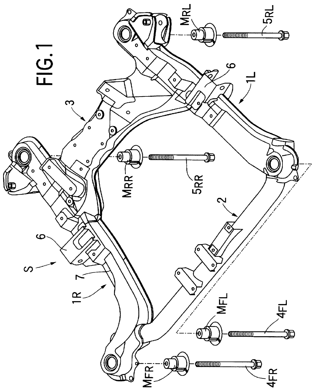
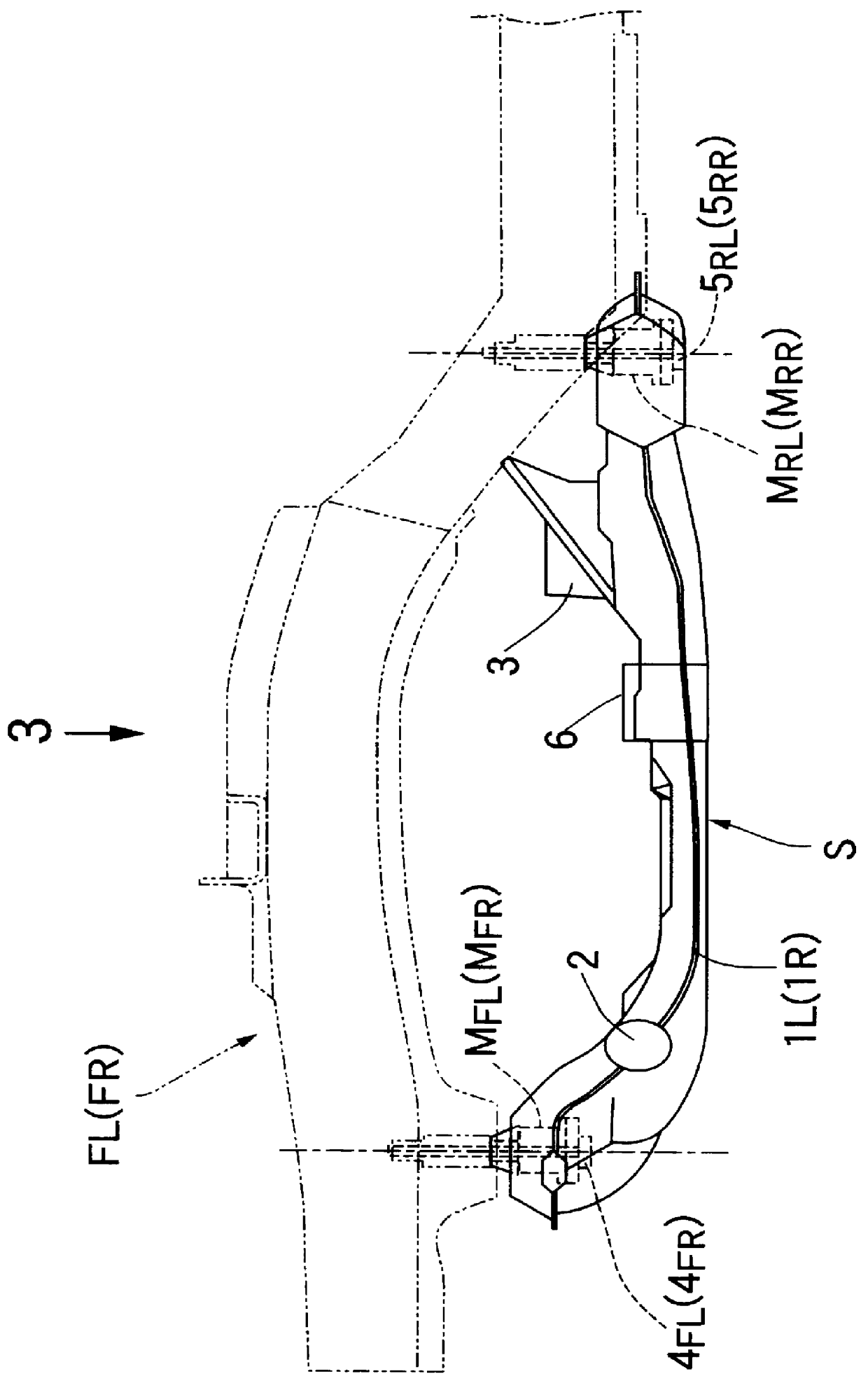
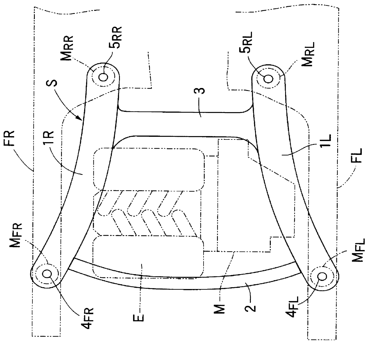
As shown in FIG. 4A, when the vehicle collides against an obstacle B substantially uniformly over its entire width, i.e., a so-called full-lap collision of the vehicle occurs, the left and right main frames FL and FR are uniformly buckled, and attendant on this, the left and right side members 1L and 1R of the front subsidiary frame S start to be buckled. In this case, the main frames FL and FR and the front subsidiary frame S are simultaneously deformed. Therefore, only a small shear force is applied to the two bolts 4.sub.FL and 4.sub.FR passed through the front rubber mounts M.sub.FL and M.sub.FR, but the two bolts 5.sub.RL and 5.sub.RR passed through the rear rubber mounts M.sub.RL and M.sub.RR are broken under the action of a large shear force. For this reason, the rear portion of the front subsidiary frame S is separated from the main frames FL and FR.

Alternatively, the rear po...

second embodiment

The front subsidiary frame S' is provided with a difference in rigidity by mounting a reinforcing member 8 within a left sided member 1L' without providing a difference in rigidity between left and right side members 1L' and 1R' themselves. More specifically, an upper member 9 and a lower member 10 are welded to each other at flanges 9.sub.1, 9.sub.1 and 10.sub.1, 10.sub.1 to form the left side member 1L' having a box-shaped section, and the reinforcing member 8 made by pressing a steel plate is welded to an inner surface of the upper member 9, thereby enhancing the rigidity of the left side member 1L'.

Even with the second embodiment, the two bolts 5.sub.RL and 5.sub.RR passed through the left and right rear rubber mounts M.sub.RL and M.sub.RR can be separately broken with a time lag therebetween under an influence of a difference in rigidity between the left side member 1L' having the reinforcing member 8 and the right side member 1R' having no reinforcing member, thereby suppress...


PUM


Abstract

A shock absorbing vehicle body structure in a vehicle includes a substantially quadrilateral front subsidiary frame comprised of left and right side members extending in a longitudinal direction of a vehicle body and connected at their front and rear ends to each other by a front cross member and a rear cross member. The front subsidiary frame is supported at its four corners on main frames for the vehicle body through rubber mounts and bolts. Upon full-lap collision of the vehicle, the left rear bolt is first broken, whereby the rear end of the left side member is separated from the main frame and then, the right rear bolt is broken, whereby the rear end of the right side member is separated from the main frame. The right and left side members are formed with different rigidities to a longitudinal load applied thereto, which causes the right and left rear bolts to break at different times, or with a time lag therebetween. Such a time lag decreases the peak value of deceleration of the vehicle at a time when the front subsidiary frame is separated from the main frames due to a full-lap collision of the vehicle.

Description

1. Technical Field to Which the Invention BelongsThe present invention relates to a shock absorbing vehicle body structure in a vehicle including a front subsidiary frame supported on a main frame.2. Discussion of Relevant ArtA shock absorbing vehicle body structure in a vehicle including a front subsidiary frame supported on a vehicle body is known from Japanese Utility Model Application Laid-open No. 52-11717. According to such known structure an arrangement is disclosed whereby, in order to prevent a vehicle compartment from being deformed by the front subsidiary frame upon frontal collision of the vehicle, bolts for coupling a rear end of the subsidiary frame to the vehicle body are broken and cut away from the vehicle body.When the front subsidiary frame resists a compressing load inputted thereto from the front due to collision of the vehicle, the deceleration of the vehicle is increased. When the front subsidiary frame becomes separated from the vehicle body as a result of th...

Claims


Application Information

Patent Timeline
Patent Type & Authority Patents(United States)
IPC IPC(8): B62D21/11B62D21/15B62D25/20B60R21/02B62D21/00B62D21/02B62D21/12
CPCB62D21/11B62D21/152B60G2204/15B60G2206/016B60G2206/604
Inventor YAMAMOTO, HIDEHIROKANDA, MINORU
Owner HONDA MOTOR CO LTD
Why Eureka
Try Eureka