Lubricating structure of transmission

a technology of transmission and lubricating structure, which is applied in the direction of gear lubrication/cooling, friction gearings, gearings, etc., can solve the problems of difficult to supply sufficient oil to these portions, and inability to feed oil to the feed path o,

Inactive Publication Date: 2000-08-29
NISSAN MOTOR CO LTD
View PDF10 Cites 34 Cited by
  • Summary
  • Abstract
  • Description
  • Claims
  • Application Information

AI Technical Summary

Benefits of technology

The present invention was made in response to the needs mentioned above, and it is an object to provide a lubricating structure of a transmission capable of increasing the amount of oil introduced into the feed path within the counter shaft thereby to supply sufficient oil to various portions.

Problems solved by technology

However, in such a lubricating structure of the transmission, the forming of the oil path p through the case n is troublesome, and furthermore, there is a drawback in that because the oil pump is not driven while the vehicle is towed by another vehicle, it is impossible to feed oil to the feed path o, and thus to various portions.
In particular, in the toroidal transmission mechanism as shown in FIG. 5, because the output gear c, the first counter gear e and the bearing g are disposed in a narrow space between the pair of output disks r having their rear portions opposing to each other, it is difficult to supply sufficient oil to these portions.

Method used


Image

  • Lubricating structure of transmission
  • Lubricating structure of transmission
  • Lubricating structure of transmission

Examples


Embodiment Construction

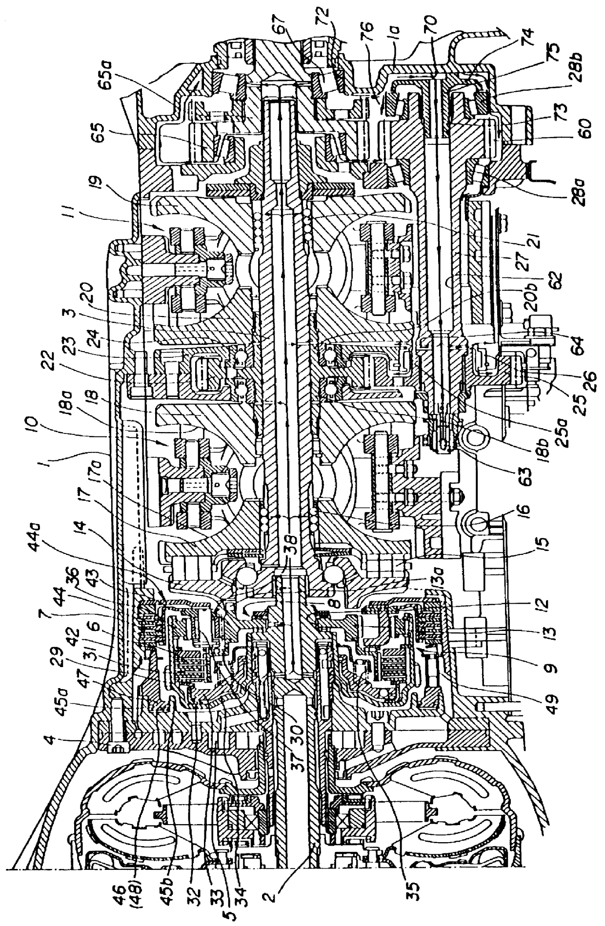
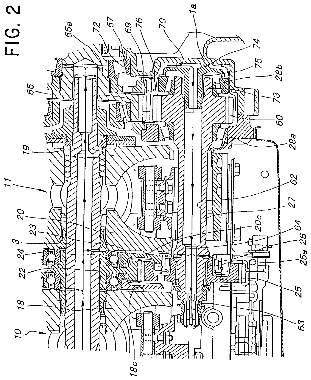
As shown in FIGS. 1 and 2, an input shaft 2 connected to a rotary driving source (not shown), and a rotary shaft 3 arranged concentrically with the input shaft 2 at a right side thereof are disposed within a transmission case 1, and at a input shaft 2 side, there are provided with an oil pump 5 mounted on an end portion of the transmission case 1 with a bolt 4, and a forward and backward change-over mechanism 9 disposed adjacent to the oil pump 5 at a right side thereof. The forward and backward change-over mechanism 9 performs change-over between a forward operation and a backward operation of a first and a second toroidal transmission mechanism 10,11 through a planetary gear mechanism 8 by manipulation of a forward clutch 6 and a backward brake 7. Furthermore, at an output shaft 3 side, there are provided with the first and the second toroidal transmission mechanism 10, 11 spaced from each other in the axial direction.

Between the input shaft 2 and the rotary shaft 3, there are int...


PUM


Abstract

A lubricating structure comprises an output gear 22 rotating as a unit with an output shaft 3 of a transmission mechanism, a gear 25 rotating as a unit with a counter shaft 27 and engaged with the gear 22, a gear 60 rotating as a unit with the shaft 27 and disposed spaced from the gear 25 in an axial direction, a bearing 26 and bearing 28b for rotatably supporting the shaft 27 respectively at a gear 25 side and a gear 60 side, a driving gear 65 disposed above the gear 60 and engaged with the gear 60 through an intermediate gear, a case 1a for individually accommodating through a separating wall the bearing 28b, a bearing at an intermediate gear side, and a bearing 67 at a gear 65 side, and feed paths 62,64 formed within the shaft 27 for introducing oil moved into an accommodating portion 70 of the gear 28b in the case 1a to a gear 25 side thereby to supply the oil to a predetermined portion. Furthermore, a void groove 76 is formed in the separating wall 69 between the accommodating portion 70 and an accommodating portion at an intermediate gear side.

Description

BACKGROUND OF THE INVENTION1. Field of the InventionThe present invention relates to a lubricating structure of a transmission, and in particular, to a lubricating structure suitable for a toroidal type infinitely variable automatic transmission.2. Description of the Related ArtA lubricating structure of a transmission of this type known in the art is described, for example in Japanese Patent Laid Open Publication Hei No.3-92655. This lubricating structure is applied to a toroidal type infinitely variable automatic transmission, and as shown in FIG. 5, this lubricating structure comprises an output gear c provided coaxially with a rotary shaft b of the toroidal transmission mechanism a and rotating as a unit with an output shaft q which transmits power of an output disks r, a first counter gear e rotating as a unit with a counter shaft d disposed in parallel with the rotary shaft b and engaged with the output gear c, a second counter gear f disposed spaced from the first counter gea...

Claims


Application Information

Patent Timeline
Patent Type & Authority Patents(United States)
IPC IPC(8): F16H57/04F16H15/38
CPCF16H57/043F16H57/0426Y10T74/2186F16H57/049
Inventor NAGAI, MASAYUKIMORI, HARUHITONAKANO, MASAKI
Owner NISSAN MOTOR CO LTD
Why Eureka
Try Eureka