Manoeuvre equipment for rods used in drilling plants

Inactive Publication Date: 2000-09-05
SOILMEC
View PDF25 Cites 10 Cited by
  • Summary
  • Abstract
  • Description
  • Claims
  • Application Information

AI Technical Summary

Benefits of technology

It is an object of the present invention to provide an improved and mechanised rod-manoeuvring equipment that can make the above men

Problems solved by technology

This type of equipment allows good handling of the rods yet it presents the inconvenience that the presence of an operator is needed in order to manually fasten, to the fastening device of the crane, each single rod that is to be taken out from the

Method used


Image

  • Manoeuvre equipment for rods used in drilling plants
  • Manoeuvre equipment for rods used in drilling plants

Examples


Embodiment Construction

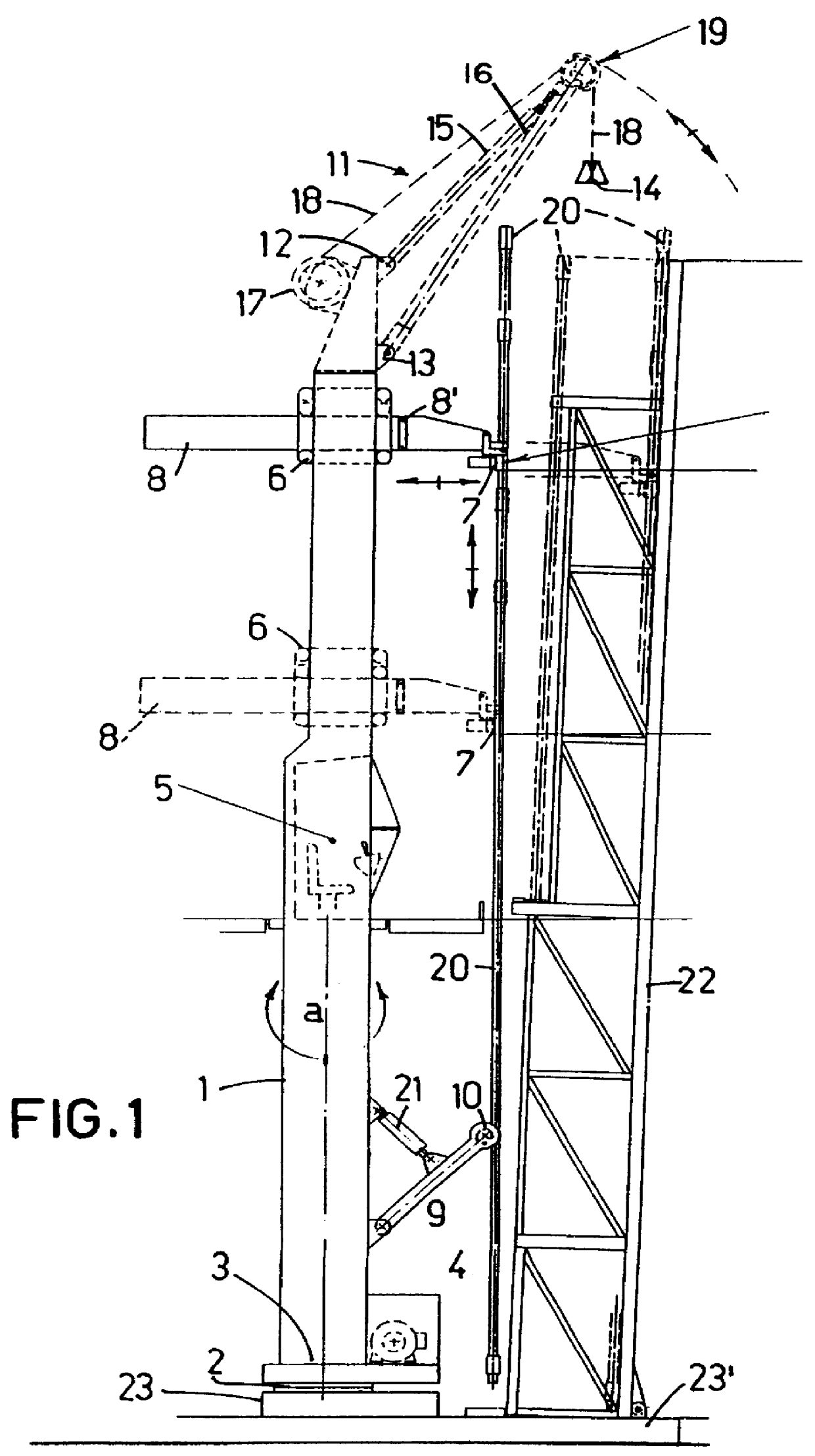
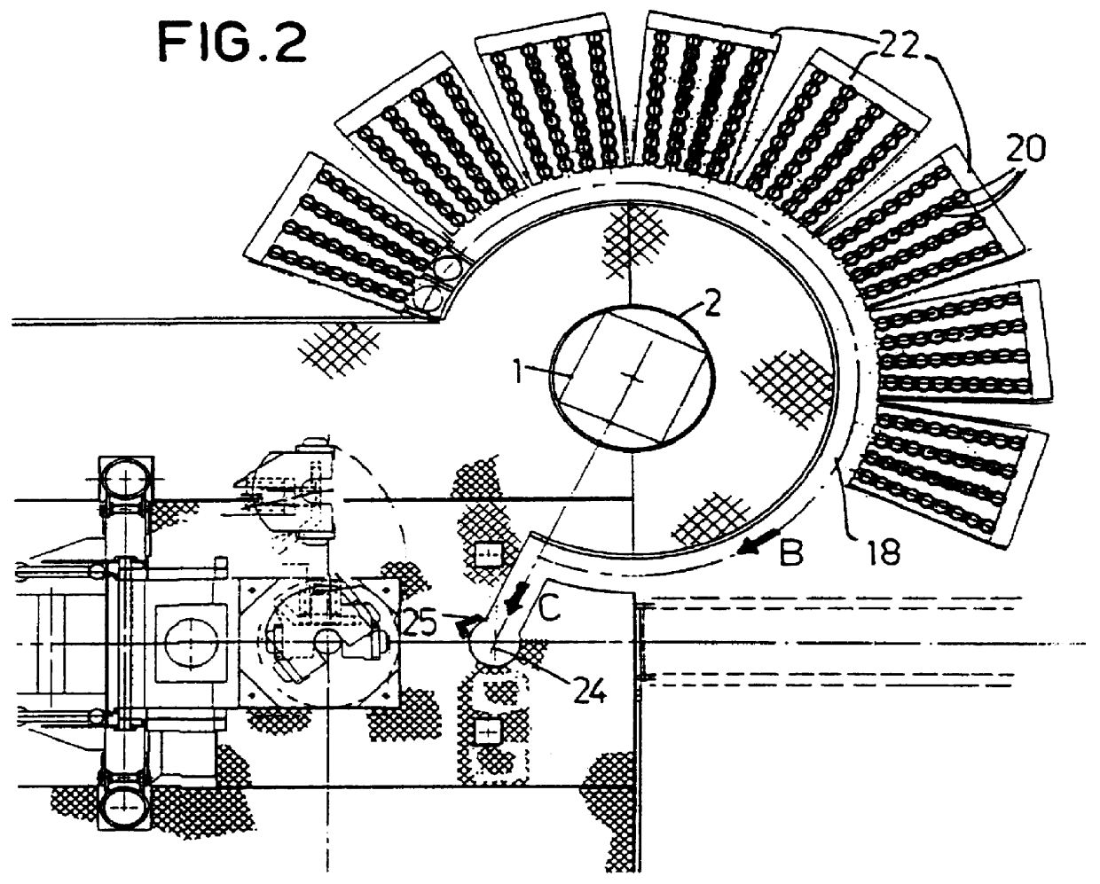
With reference to FIG. 1, number 1 indicates the vertical column 1, provided with its own base 3 rotating on a vertical axis a; on the base 3, near the foot of the column, it is also secured an electrohydraulic gearcase 4 with its relative oil tank and electric control panel. An horizontal fifth wheel 2, coaxial to the axis a, is placed vertically between the rotating base 3 and a fixed base 23 rigidly fixed to the rigid base 23' to which the lattice containers 22 for the drilling rods 20 are secured all around the rotation axis a of the column, as described in the mentioned Patent Application for Utility Model n.degree. TO92U000228.

A cabin 5 for the operator is located at nearly half the height of the column 1.

Along the vertical column 1 slides a saddle 6 that supports in horizontally sliding way a horizontal arm 8 on the end of which--and facing the containers 22--there are the hydraulic clamping pliers 7 to fasten each rod 20 that is to be manoeuvred.

In the lower part of the colu...


PUM


Abstract

Description of a manoeuvre equipment for rods (20) used in drilling plants, operating between an equipment for rod stowage (22, 23), where lines of rods are stowed vertically, and a service well (24) from which each single rod (20) can be taken out, and in which each single rod can be placed in, by means of a mobile motive head of the drilling head of the plant. The manoeuvre equipment includes a column (1). rotating on its vertical axis (a); the column supports, rotating rigid with it: pliers (7) to lock a single rod (20); one saddle (6) to translate the pliers (7) according to a vertical axis parallel to the (a) axis; one horizontal arm, sliding inside the saddle (6), that translates the pliers (7) according to a horizontal axis perpendicular to the (a) axis; means (9, 10, 21) to adjust the verticality of the rod (20) locked by the pliers (7).

Description

DESCRIPTIONThe present invention relates to a manoeuvre equipment for rods used in soil drilling plants.DESCRIPTION OF THE STATE OF THE ARTOne of the systems currently used to mount single rods on the rod string, consists in making, next to the drilling hole, a service well from which a new drilling rod to be fixed on the motive head of the plant is cyclically taken. The head is then lifted upwards together with the new rod and placed again in axis with the drilling hole, the new drilling rod is connected to the rods already operating and the drilling of a new portion of the same length of the newly mounted rod is started.From the Italian Patent Application for the Utility Model n.degree.TO92U000228, on behalf of the same Petitioner, it is known an equipment to stow and manoeuvre rods for soil drilling plants which include a drilling tower with motive head that moves between a drilling hole and one service well used to take and place the drilling rods. Such equipment includes a rigi...

Claims


Application Information

Patent Timeline
IPC IPC(8): E21B19/14E21B19/00
CPCE21B19/14
Inventor RIVA, GIOVANNI
Owner SOILMEC
Why Eureka
Try Eureka