Rotary mirror assembly having spherical housing

a mirror and spherical technology, applied in the field of mirror assemblies, can solve the problems of degrading the performance of the rotating mirror, attracting very fine particles of dust, and mirror noise generated, and achieve the effect of reducing noise generation

Inactive Publication Date: 2000-10-10
THE GSI GRP LLC
View PDF11 Cites 3 Cited by
  • Summary
  • Abstract
  • Description
  • Claims
  • Application Information

AI Technical Summary

Benefits of technology

An aim of the present invention is to overcome the above disadvantages and reduce to a minimum the noise generation of a high speed rotating mirror, as well as to prevent the deposition of small particles of dust on the mirror surface.

Problems solved by technology

The disadvantage of such housings is the question of noise generated from the mirror which, hitherto required a significant level of sound proofing of the image setting machine in order to reduce the noise level to an acceptable level.
Another disadvantage of such housings is that a rotating mirror attracts very fine particles of dust which become deposited on the mirror during operation at high speeds of rotation.
These particles of dust significantly degrade the performance of the rotating mirror.

Method used


Image

  • Rotary mirror assembly having spherical housing
  • Rotary mirror assembly having spherical housing
  • Rotary mirror assembly having spherical housing

Examples


Embodiment Construction

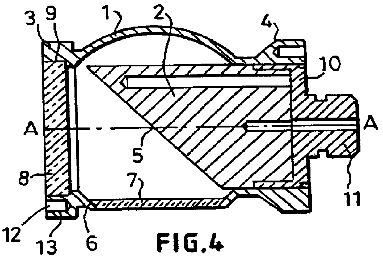
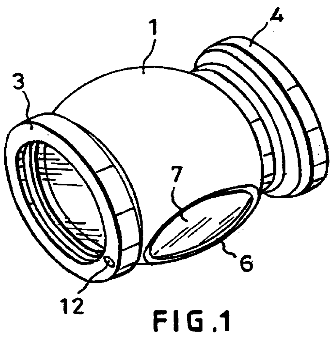
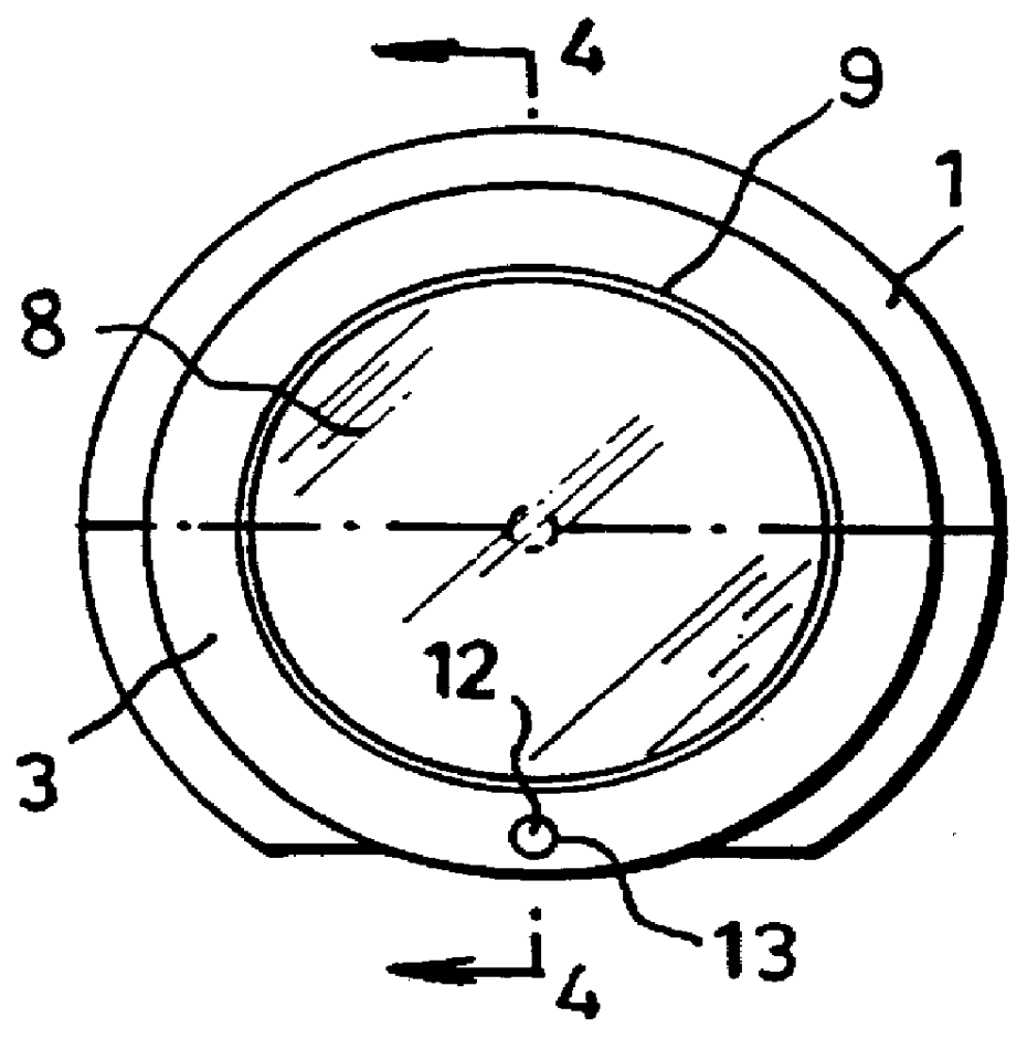
The mirror assembly comprises a spherical shaped housing 1 rotatable about an axis "A", see FIG. 4. The housing contains a mirror 2 bonded by an adhesive e.g. ARALDITE 2003 (Registered Trade Mark) in the rear end of the housing. The end of the housing at the front of the mirror 2 has a flange 3, while a second enlarged flange 4 is formed at the rear of the mirror 2.

The front of the mirror 2 has a sloping end face 5 inclined at an angle of 45.degree. to the rotary axis "A" which faces towards an opening 6 in the side of the spherical housing.

Due to the natural degree of distortion, due to the rotation of the window from an optical viewpoint, it is therefore essential to minimize this adverse effect. Of the available materials it has been found that sapphire is used as it has a high Youngs Modulus / density ratio. Accordingly the opening is closed by an optically flat sapphire window 7 bonded into the opening using an adhesive, e.g. ARALDITE 2003 (Registered Trade Mark). The front of th...


PUM


Abstract

A rotatable mirror assembly is described comprising a spherical housing (1) rotatable about an axis (A). The housing contains a mirror (2) bonded in the rear end of the housing. The housing at the front of mirror (2) has a flange (3) while a second enlarged flange (4) is formed at the rear of the mirror (2) the front of the mirror (2) has a sloping end face (5) at an angle of 45.degree. of the rotary axis (A) which fives toward an opening (6) in the side of the housing (1). The opening (6) in a first embodiment is closed by an optically flat sapphire window (7) bonded into the opening (6) and in a second embodiment has a curved lens (17) mounted in the aperture. The improved assemblies reduce noise generation of high speed rotating mirrors and prevent the deposit of small particles of dust on the mirror surface.

Description

BACKGROUND OF THE INVENTION1. Field of the InventionThis invention relates to a mirror assembly and more particularly to a mirror assembly in the field of image setting, which is rotatable at high speed.2. Description of the Related ArtIn the field of image setting the typical requirement is for the high speed rotation of a mirror in a housing which is normally formed to have a face nominally at 45.degree. to the axis of rotation of the housing.The disadvantage of such housings is the question of noise generated from the mirror which, hitherto required a significant level of sound proofing of the image setting machine in order to reduce the noise level to an acceptable level.Another disadvantage of such housings is that a rotating mirror attracts very fine particles of dust which become deposited on the mirror during operation at high speeds of rotation. These particles of dust significantly degrade the performance of the rotating mirror.SUMMARY OF THE INVENTIONAn aim of the present...

Claims


Application Information

Patent Timeline
Patent Type & Authority Patents(United States)
IPC IPC(8): G02B26/08G02B7/182
CPCG02B7/1821
Inventor TEMPEST, MICHAEL C.
Owner THE GSI GRP LLC
Why Eureka
Try Eureka