
Fan frame and fan module

a technology of fan frame and fan module, which is applied in the direction of machines/engines, stators, liquid fuel engines, etc., can solve the problems of reduced comfort, undesired noise generation, and increased noise generation, and achieve the effect of sufficient shielding and/or separation

Active Publication Date: 2016-01-21
BROSE FAHRZEUGTEILE GMBH & CO KG HALLSTADT (DE)
View PDF5 Cites 0 Cited by
  • Summary
  • Abstract
  • Description
  • Claims
  • Application Information

AI Technical Summary

Benefits of technology

The present invention provides a fan with a shielding device to prevent the influence of flows in the outflow region of another fan, which reduces noise generation and the need for additional air output capacity. The shielding device is designed as a partition portion that is integrally formed with the fan frame and can be produced without the need for additional steps. The partition portion surrounds the first and additional fan brackets and is positioned to prevent negative influences on each other. The advantage of the invention is that it achieves minimal noise generation and optimal air output capacity without having to compromise the air output.

Problems solved by technology

In parallel operation using both fans, in double-fan modules a higher level of noise generation may occur, and users usually find this unpleasant, which reduces the level of comfort.
However, in this case the outflows from the two fans may interfere with each other, and this may again result in undesired noise generation.
By completely surrounding the fan, the air output (volume- or mass flow of the air) is reduced, however, since the outflow to the side is restricted.

Method used


Image

  • Fan frame and fan module
  • Fan frame and fan module
  • Fan frame and fan module

Examples


Embodiment Construction

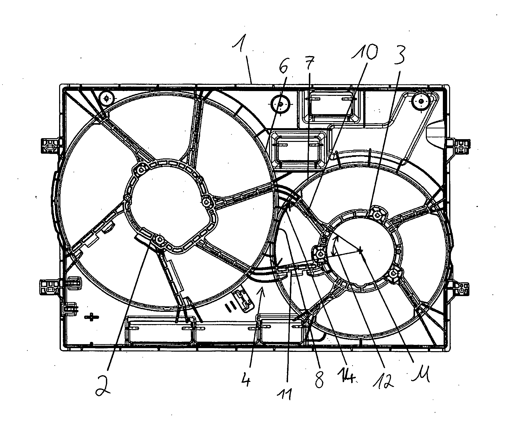
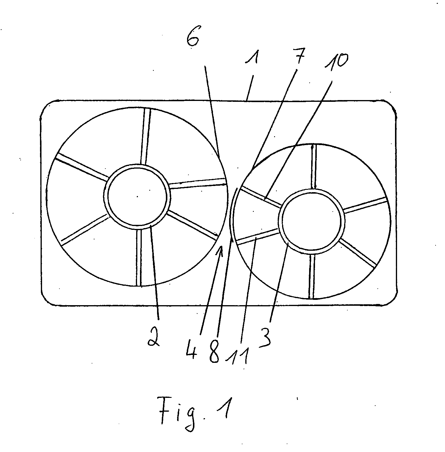
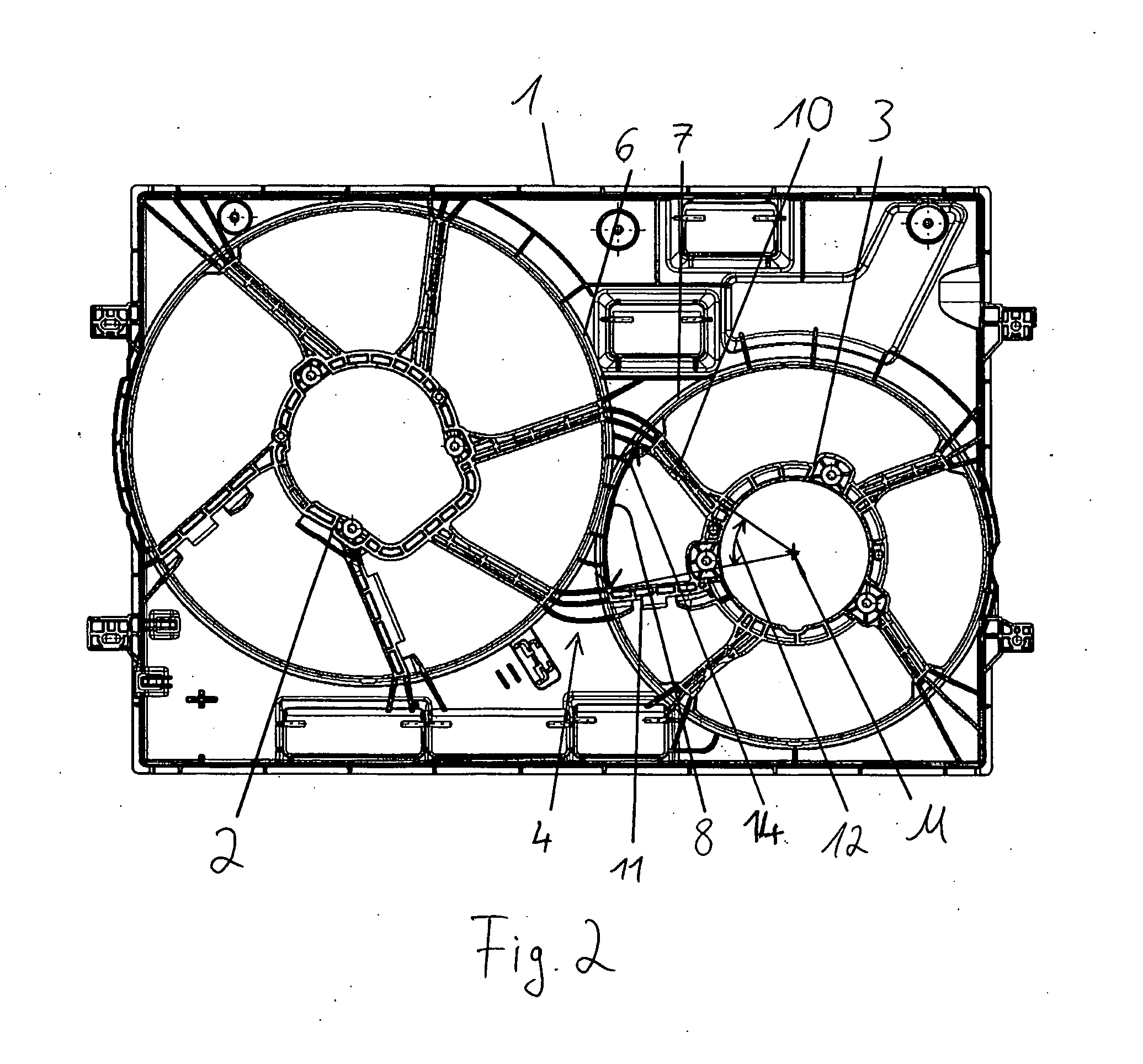
[0040]FIG. 1 is a schematic view of a fan frame 1 according to the invention. Said frame comprises a first bracket 2 and an additional, preferably second, bracket 3, which are each designed to mount a fan in the fan frame 1. The brackets 2, 3 each have an edge region 6, 7 and attachment struts 10, 11. The attachment struts 10, 11 open into a retaining ring, which is designed for attaching a fan. An intermediate region 4 which interconnects the edge regions 6, 7 is provided in the frame 1 between the two brackets 2, 3.

[0041]The fan frame 1 has two sides, namely an intake side and a discharge side, FIG. 1 showing the discharge side. Said frame is provided such that a fan which is installed in the brackets 2 and 3 discharges the air it takes in on this side. In the figure, the respective outflow regions of the brackets 2 and 3 can thus be seen. A shielding device 8 is provided in the intermediate region 4 between the two brackets 2 and 3. Said shielding device is arranged and designed ...


PUM


Abstract

The present invention relates to a fan frame for a plurality of fan modules, particularly for a radiator of a motor vehicle, comprising a first fan holder having a first outflow region, at least one further fan holder having a further outflow region, and an intermediate region that connects adjoining edge regions of the first and the further fan holders to each other. The fan frame is characterised in that a shielding device, which separates the first and a further outflow region from each other, is provided in the intermediate region. The present invention further relates to a fan module, particularly having such a fan frame.

Description

FIELD OF THE INVENTION[0001]The present invention relates to a fan frame for a plurality of fan modules. The invention further relates to a fan module.TECHNICAL BACKGROUND[0002]Although the present invention is described with reference to a fan module for a motor vehicle, it is not limited thereto, but can also be applied to other technical fields.[0003]A fan module in a motor vehicle is used for thermal management. The fan module is generally provided on a radiator or heat exchanger in order to transport an air flow through the radiator and to thus ensure sufficient cooling, for example in stop-and-go traffic, if there is not a sufficient airstream.[0004]A fan module typically comprises an externally driven fan or ventilator which usually conveys and compresses air by means of an impeller which rotates in a frame.[0005]In order to ensure optimal utilisation of the radiator surface in substantially rectangular or non-square radiators, double-fan modules are sometimes used which comp...

Claims


Application Information

Patent Timeline
IPC IPC(8): F04D29/52F01P1/06F01P5/02F04D19/00
CPCF01P5/02F01P11/10F04D29/522F01P1/06F04D19/002F01P2005/025
Inventor SPRINGER, NILSDREESEN, THOMASFINDEISEN, ANTJE
Owner BROSE FAHRZEUGTEILE GMBH & CO KG HALLSTADT (DE)
Learn More