Optical active connector

a technology of optical active connectors and active connectors, applied in the direction of optical elements, coupling device connections, instruments, etc., can solve the problems of erroneous signals, electromagnetic noise emitted by vehicles affecting the surroundings, and insufficient consideration of electromagnetic noise countermeasures

Inactive Publication Date: 2007-03-06
AUTONETWORKS TECH LTD +2
View PDF6 Cites 4 Cited by
  • Summary
  • Abstract
  • Description
  • Claims
  • Application Information

AI Technical Summary

Benefits of technology

[0011]In order to achieve the above-described object, exemplary embodiments of the invention provide an optical active connector for converting between an optical signal and an electric signal in a communication path in a vehicle. The optical active connector includes an electric connector portion for executing at least one of an input and an output of the electric signal, an optical element for executing an input or an output of the optical signal, a mounting board having a circuit for executing a predetermined signal conversion and relay processing between the electric connector portion and the optical element, and a case holding the electric connector portion, the optical element and the mounting board. The case is formed with an optical element-containing recessed portion having electrical conductivity, and the optical element is arranged in the optical element-containing recessed portion. According to this structure, an electromagnetic wave can sufficiently be shielded from leaking from the optical element to outside, or from coming from outside to the optical element.
[0012]In exemplary embodiments, the case may be formed with a mounting part-containing recessed portion having electrical conductivity, independently from the optical element-containing recessed portion, and a mounting part mounted to the mounting board may be arranged in the mounting part-containing recessed portion. According to this structure, an electromagnetic wave can sufficiently be shielded from leaking from the mounting part on the mounting board to outside, or from coming from outside to the mounting part. Further, because the optical element-containing recessed portion and the mounting part-containing recessed portion are formed independently from each other, electromagnetic shielding is achieved also between the optical element and the mounting part.

Problems solved by technology

However, the above-described optical active connector is on the premise of a transmission speed of about several megabits per second and on the premise of use by a general civil apparatus, and therefore, sufficient consideration is not given to a countermeasure against electromagnetic noise that is present in use of a vehicle.
For example, in vehicular optical communication necessitating a transmission speed exceeding 100 megabits per second, electromagnetic noise emitted by a vehicle affects the surroundings, and erroneous signals are introduced by electromagnetic noise received from the surroundings.

Method used


Image

  • Optical active connector
  • Optical active connector
  • Optical active connector

Examples


Embodiment Construction

[0022]An explanation will be given of an optical active connector according to an embodiment of the invention as follows.

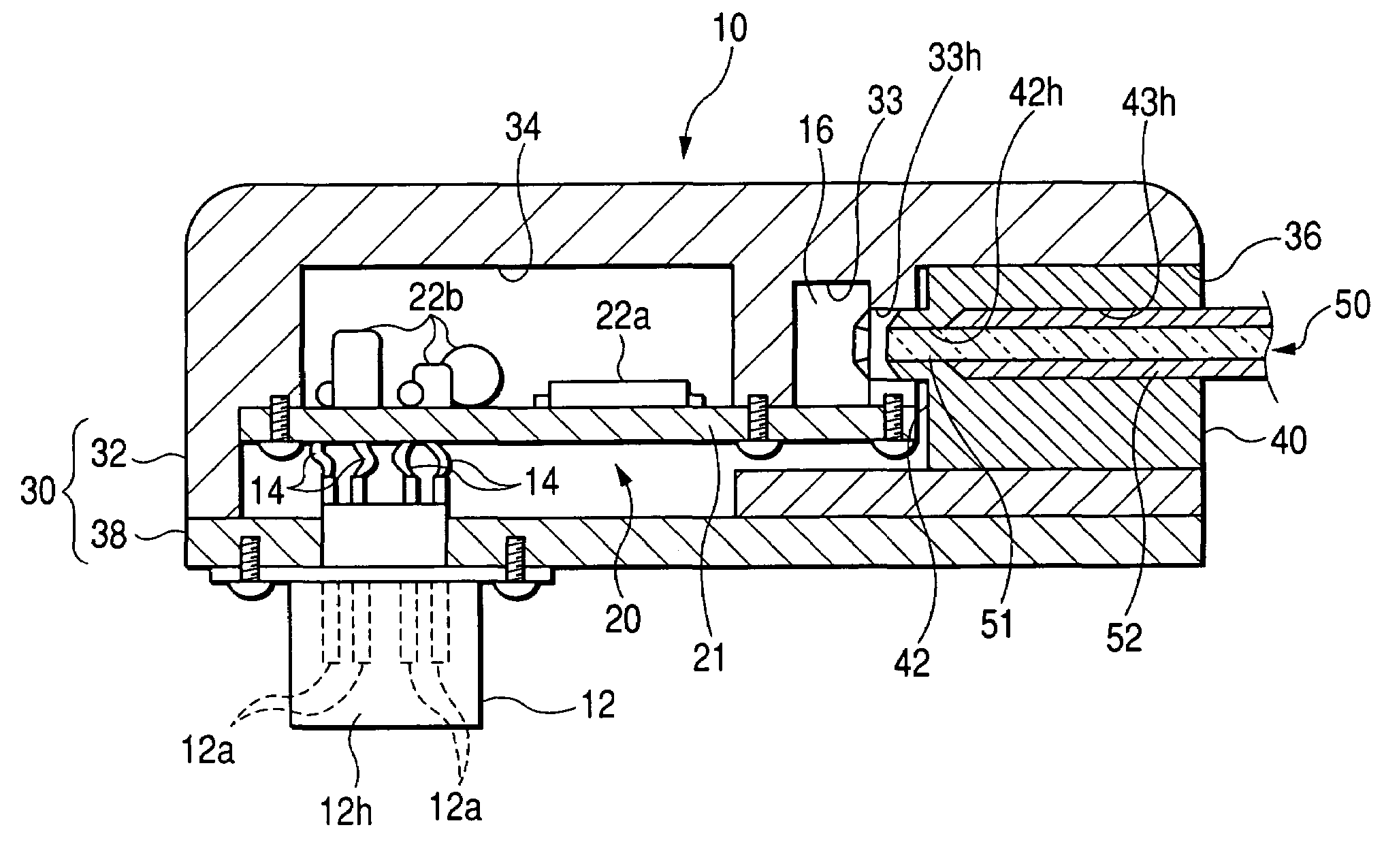
[0023]FIG. 1 is a sectional view showing an optical active connector. The optical active connector 10 is provided with an electric connector portion 12, an optical element 16, a mounting board 20, a case 30, and an optical fiber fixing portion 40.

[0024]The case 30 is provided with a case main body portion 32 substantially in a shape of a cabinet, one side of which is open, and a lid portion 38 closing an opening of the case main body portion 32. The case main body portion 32 and the lid portion 38 may be members made of a metal by diecasting, or shaped by any other suitable metalworking method, or may be members of an electrically conductive resin mixed with a conductive filler such as a metal filler or the like, such that, as a whole, they are electrically conductive. As an alternative, only an optical element-containing recessed portion 33 and a mounting part-co...


PUM


Abstract

An electric connector portion, an optical element and a mounting board formed with a circuit executing a predetermined signal conversion and relay processing are held by a case. The case includes an optical element-containing recessed portion having electrical conductivity, and the optical element is arranged in the optical element-containing recessed portion. Further, the case may include a mounting part-containing recessed portion independently from the optical element-containing recessed portion, and mounting parts on the mounting board may be arranged in the mounting part-containing recessed portion.

Description

[0001]The disclosure of Japanese Patent Application No. JP2003-350984 is incorporated herein by reference in its entirety.BACKGROUND OF THE INVENTION[0002]1. Field of Invention[0003]The present invention relates to a technology of an optical active connector, particularly useful for high speed optical communication in, for example, a vehicular optical communication system.[0004]2. Description of Related Art[0005]In general civil apparatus, there is known an optical active connector (integrated type plug) integrated with an interface for an electric cable, an interface for an optical fiber or an interface with a photoelectric conversion unit.[0006]Such an optical active connector is interposed between an electric apparatus and an optical fiber cable, between an electric cable and an optical fiber cable, or the like for converting between electric signals and optical signals in a communication path between predetermined electric apparatus.[0007]Such an optical active connector is disc...

Claims


Application Information

Patent Timeline
Patent Type & Authority Patents(United States)
IPC IPC(8): G02B6/42G02B6/36H01R13/648H01R13/66H05K9/00
CPCG02B6/4201
Inventor YUUKI, HAYATO
Owner AUTONETWORKS TECH LTD
Why Eureka
Try Eureka