Method for generating a component by a power-bed-based additive manufacturing method and powder for use in such a method

Active Publication Date: 2019-06-27
SIEMENS ENERGY GLOBAL GMBH & CO KG
View PDF0 Cites 3 Cited by
  • Summary
  • Abstract
  • Description
  • Claims
  • Application Information

AI Technical Summary

Benefits of technology

[0020]The shell of the particles of the single-crystal alloys may include tungsten and/or tantalum. To achieve an extremely high melting point in the shell, it is possible according to one advantageous embodiment for the shell to consist to an extent of more than 99 mass %, or completely, of a single metallic alloy element. Consisting completely of one alloy element, however, strains the bounds of what is technically possible, and so up to one mass % of other alloy constituents may be allowed. The advantage of generating the shell only from a single metallic alloy element is that the shell contains substantially no alloy compositions which, owing to formation of eutectic mixtures, normally have a lower melting point than their elemental alloy constituents. As a result, it is possible advantageously to raise the melting temperature optimally through choice of the corresponding metal, specifically up to the melting temperatures (indicated) respectively above. The greatest increase in the melting temperature of the shell may be achieved, advantageously, with the alloy element of the relevant alloy composition of the particle that has the highest melting temperature.
[0021]A prerequisite for the selection of the alloy element of the shell is that this element is present to a sufficient extent in the alloy composition of the particle. In o

Problems solved by technology

In this case, however, the problem occurs that the products produced are subject to high inherent stresses, and that cracks may occur because of this fact.
This gives rise to the problem, in the case of selective laser melting, that the powder bed solidifies and may also stick to the surface of the component produced.
Cleanly removing the component produced from the powder bed is then no longer possible.
Moreover, the powder cannot be reus

Method used


Image

  • Method for generating a component by a power-bed-based additive manufacturing method and powder for use in such a method
  • Method for generating a component by a power-bed-based additive manufacturing method and powder for use in such a method

Examples


Embodiment Construction

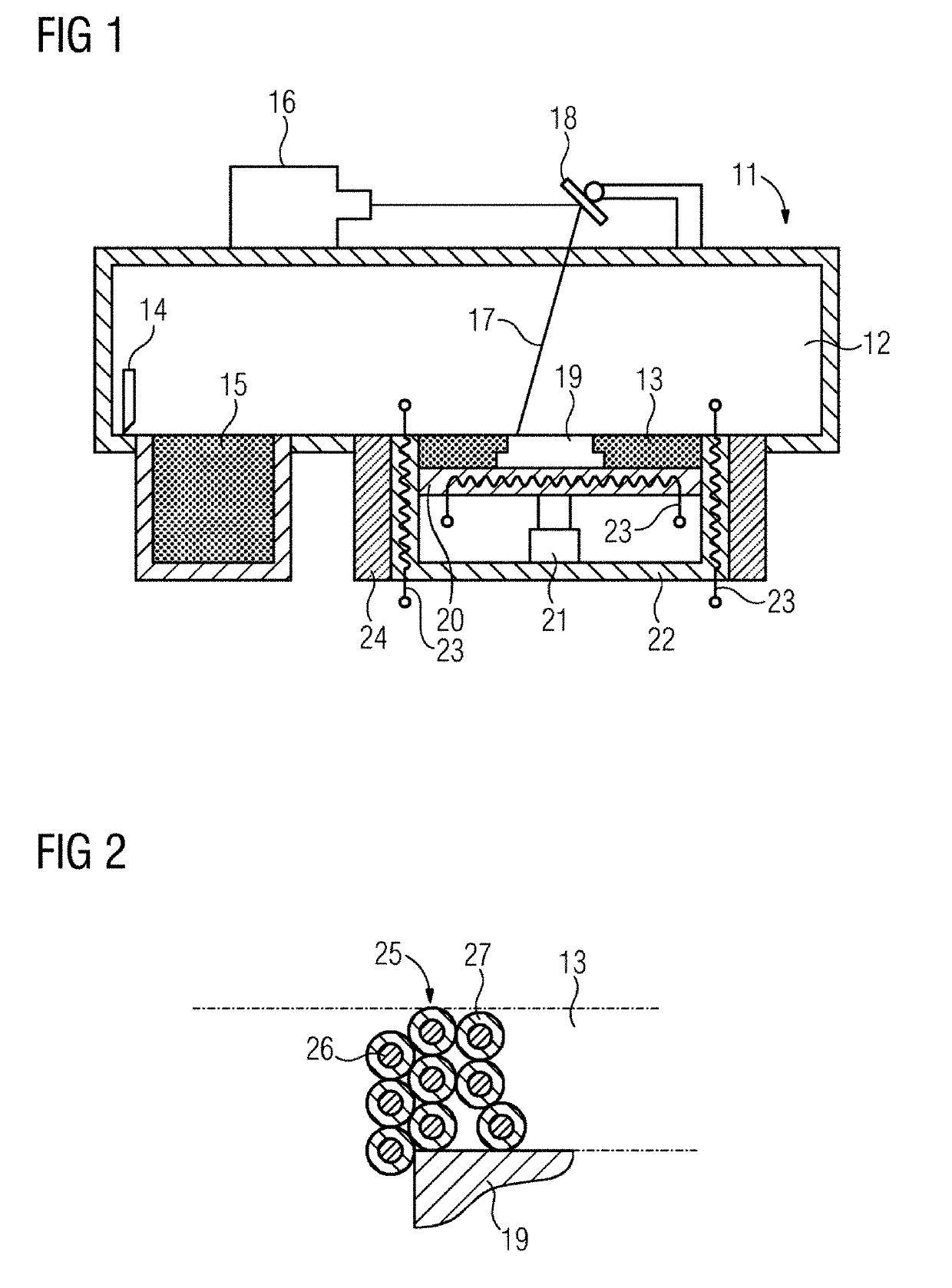
[0026]Represented schematically in FIG. 1 is a unit 11 for laser melting. This unit has a process chamber 12 in which a powder bed 13 may be produced. To produce, respectively, one layer of a powder bed 13, a spreader in the form of a doctor blade 14 moves over a powder store 15 and subsequently over the powder bed 13, so forming a thin layer of powder in the powder bed 13. A laser 16 then generates a laser beam 17, which is moved by an optical deflection apparatus with mirror 18 over the surface of the powder bed 13. At the point of impingement of the laser beam 17, the powder is melted, to form a component 19.

[0027]The powder bed 13 comes about on a building platform 20, which may be lowered step by step, by the thickness of one powder layer in each case, in a pot-shaped housing 22 by an actuator 21. In the housing 22 and also in the building platform 20, heating devices 23 are provided in the form of electrical resistance heaters (induction coils are an alternative option), which...


PUM

PropertyMeasurementUnit
Temperatureaaaaaaaaaa

Abstract

The disclosure relates to a powder and a method for generating a component by a powder-bed-based additive manufacturing method, such as laser melting. The powder includes particles having a core and a shell. The particles have an alloy composition of the component. The concentration of higher-melting alloy elements is greater in the shell and the concentration of lower-melting alloy elements is greater in the core, wherein the surface of the particles is higher in comparison with particles with a constant alloy composition. This advantageously prevents the particles from caking together in the powder bed during the production of the component, and so the powder bed may also be subjected to high preheating temperatures of up to 1000° C.

Description

[0001]The present patent document is a § 371 nationalization of PCT Application Serial No. PCT / EP2017 / 071725, filed Aug. 30, 2017, designating the United States, which is hereby incorporated by reference, and this patent document also claims the benefit of German Patent Application No. DE 10 2016 216 859.2, filed Sep. 6, 2016, which is also hereby incorporated by reference.TECHNICAL FIELD[0002]The disclosure relates to a method for generating a component, (e.g., composed of a superalloy), by a powder-bed-based additive production method. With this method, the component is built up layer by layer in a powder bed by the melting of particles forming the powder bed by an energy beam such as, for example, an electron beam or a laser beam. In this case, the powder bed is preheated to a temperature below the melting temperature of the particles, before and while the particles are melted. The disclosure further relates to a powder suitable for use in a powder-bed-based additive production m...

Claims


Application Information

Patent Timeline
IPC IPC(8): B22F3/105B22F1/02B22F1/17
CPCB22F3/1055B22F1/025B33Y70/00B22F5/009C22C1/0433Y02P10/25B22F1/17B22F10/28B22F12/44B22F12/13C22C19/00C22C27/04
Inventor BRUNHUBER, CHRISTIANSCHAFER, MARTIN
Owner SIEMENS ENERGY GLOBAL GMBH & CO KG
Why Eureka
Try Eureka