
Light-emitting device, method for producing the same, and illuminating device

a technology of light-emitting devices and led elements, which is applied in the direction of lighting and heating apparatus, discharge tube luminescnet screens, lighting support devices, etc., can solve the problems of color unevenness at those regions, insufficient effects, and more color unevenness, so as to facilitate the production of reflective portion 14, improve the thixotropic property, and facilitate the coating

Active Publication Date: 2014-06-24
STANLEY ELECTRIC CO LTD
View PDF11 Cites 5 Cited by
  • Summary
  • Abstract
  • Description
  • Claims
  • Application Information

AI Technical Summary

Benefits of technology

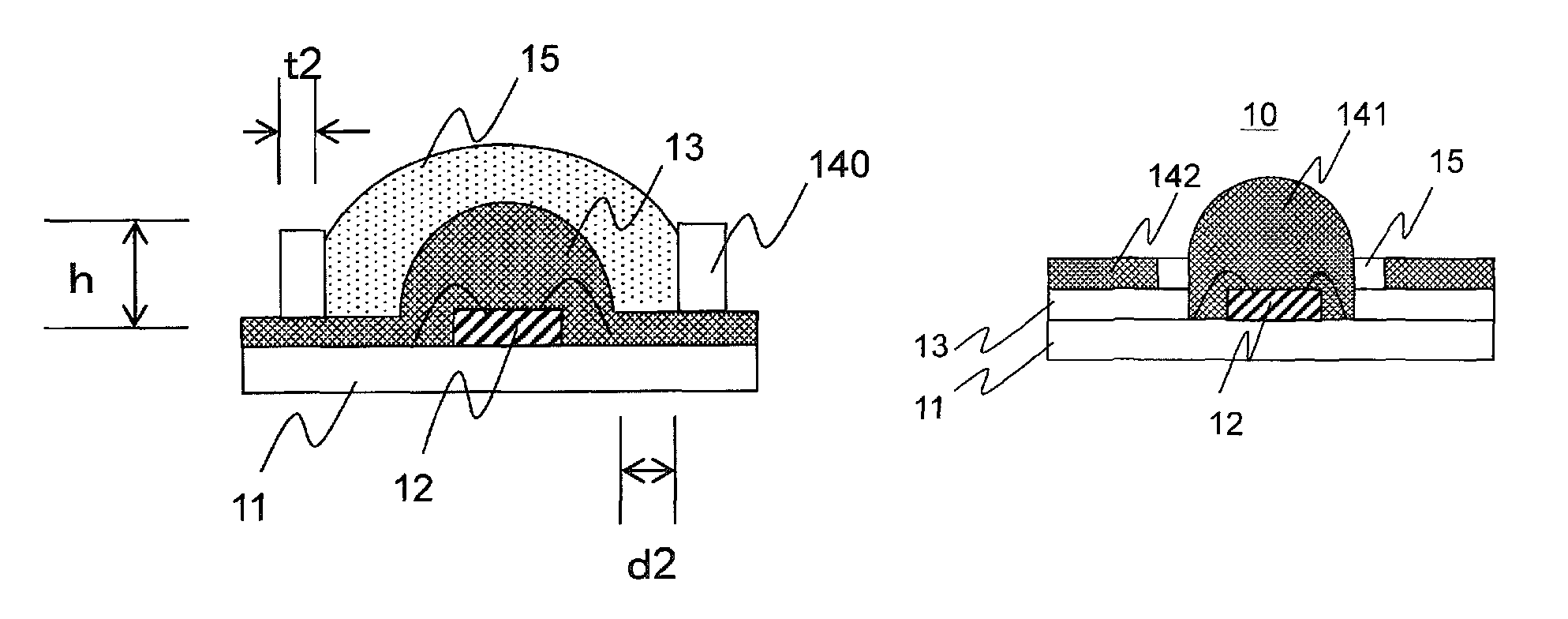
The patent text describes a lighting device that prevents color unevenness. The device includes a thin film portion of resin layer that emits light. A reflective portion is formed over the thin film portion to shield the light and direct it towards a convex portion of the device. The reflective portion can be a diffusion reflection material or a white reflective plate. The thickness of the reflective portion is set to be 0.2 mm or more. The reflective portion can be in contact with the outer periphery of the convex portion or there may be a gap between them. The device can prevent yellow light from the thin film portion from being directed towards the LED element, resulting in a more even distribution of light and no color unevenness.

Problems solved by technology

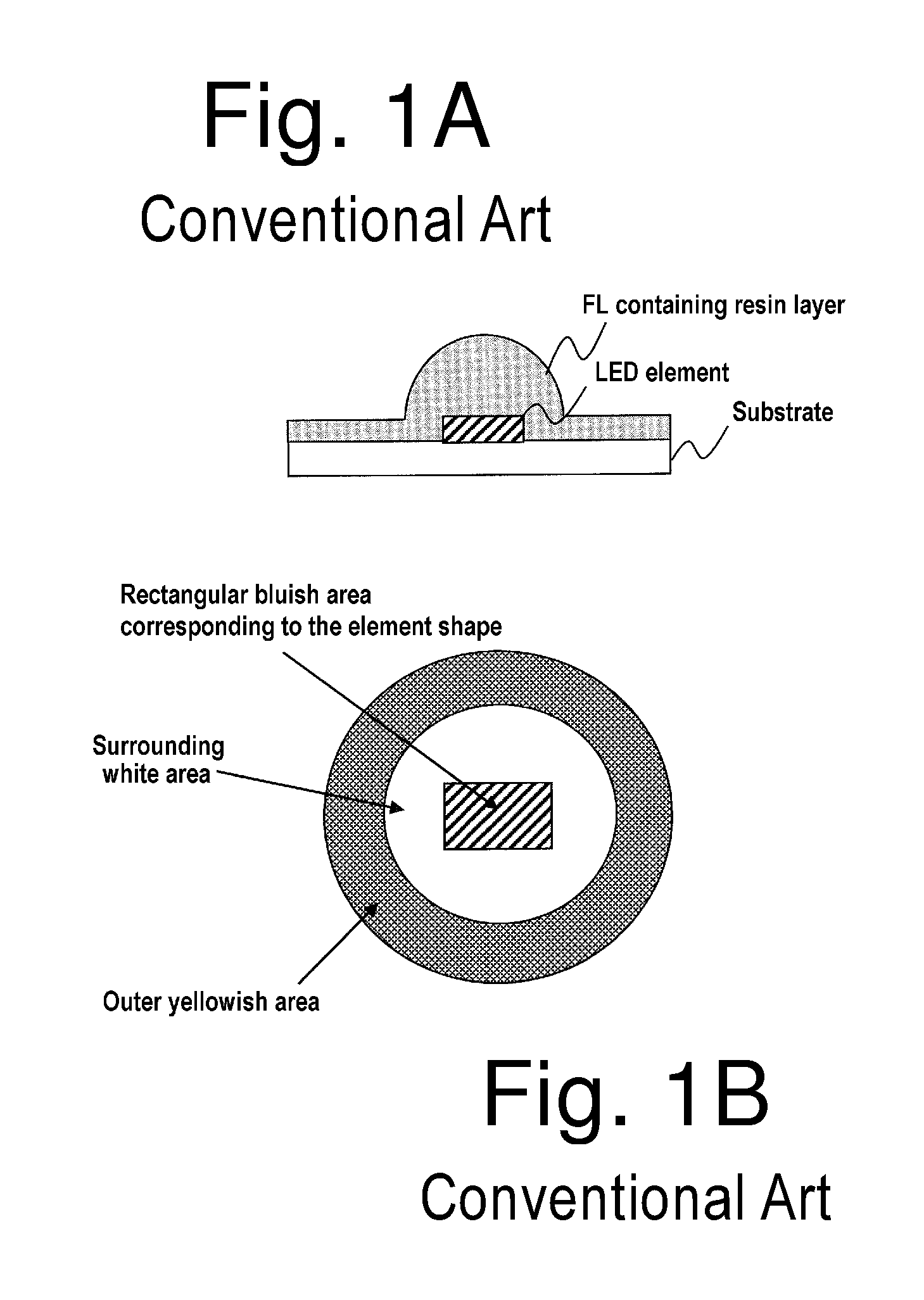
In this light-emitting device, however, the optical path length from the LED element to the top surface of a portion of the resin layer immediately above the LED element may be different from the optical path length from the LED element to the peripheral side surface of the resin layer, resulting in color unevenness at those regions.
Such a hemispherical fluorescent material layer can alleviate the color unevenness due to the difference in optical path lengths within the fluorescent material layer, but the effects are insufficient.
Therefore, the surrounding area can be observed as being more yellowish than the hemispherical portion, resulting in color unevenness more.
However, when the thin resin layer is removed by sandblasting, the hemispherical resin layer may also be damaged at the same time.
When the thin resin layer is peeled off by tape masking, the hemispherical resin layer may also be peeled off partially at the same time, resulting in decreased production yield of the light-emitting device.

Method used


Image

  • Light-emitting device, method for producing the same, and illuminating device
  • Light-emitting device, method for producing the same, and illuminating device
  • Light-emitting device, method for producing the same, and illuminating device

Examples


examples

[0144]In order to confirm the different and / or advantageous effects of the presently disclosed subject matter, the light-emitting devices with respective structures shown in FIGS. 21A to 21D were produced and the occurrence of the color unevenness was evaluated. FIG. 21A shows the same structure as that of the light-emitting device shown in FIG. 14A (Example 1), in which the substrate 11, reflector 13 and projection portion 15 were formed from a ceramic material and produced in accordance with the fourth exemplary embodiment of the production method. The thickness of the reflector 13 was 0.15 mm, and the width and the height (thickness) of the projection portion 15 were 0.1 mm and 0.05 mm, respectively. The light-emitting device shown in FIG. 21B (Comparative Example 1) was produced in the same manner as in the light-emitting device shown in FIG. 21A, except that the projection portion 15 was not provided to the light-emitting device. The light-emitting device shown in FIG. 21C (Com...


PUM


Abstract

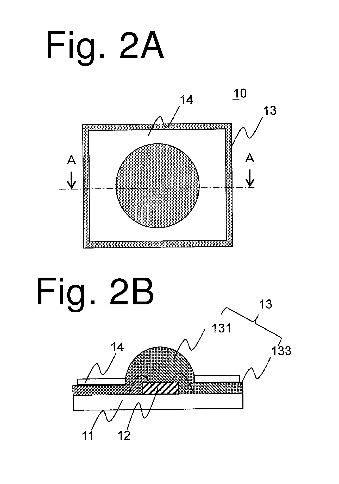
A light-emitting device having an LED element and a resin layer including a convex portion covering the LED element can suppress color unevenness to achieve light emission with uniform color distribution. The light-emitting device can include a substrate, an LED element mounted on the substrate, a resin layer which contains a wavelength conversion material and is formed on the substrate to cover the LED element, the resin layer including a convex portion directly covering the LED element and a flat thin film portion extending around the convex portion, and a reflective portion which is formed over the thin film portion around the convex portion. A diffusion portion can be formed to cover the convex portion of the resin layer.

Description

[0001]This application claims the priority benefit under 35 U.S.C. §119 of Japanese Patent Application Nos. 2011-011306 filed on Jan. 21, 2011 and 2011-063002 filed on Mar. 22, 2011, which are hereby incorporated in their entirety by reference.TECHNICAL FIELD[0002]The presently disclosed subject matter relates to a light-emitting device utilizing an LED element, a method for producing the same and an illuminating device. In particular, the presently disclosed subject matter relates to a light-emitting device including an LED element and a resin layer formed using a compression molding method and sealing the LED element to improve the color evenness.BACKGROUND ART[0003]Many light-emitting devices utilizing an LED element include a combination of an LED element and a wavelength conversion material such as a fluorescent material in order to provide light emission with desired color such as white light emission. In general, such a wavelength conversion material can be dispersed in a sea...

Claims


Application Information

Patent Timeline
Patent Type & Authority Patents(United States)
IPC IPC(8): F21V7/00F21V9/16
CPCH01L33/505H01L33/46H01L2224/45144H01L2224/48091H01L2924/0002H01L2924/00014H01L2924/00H01L33/50H01L33/52H01L33/60
Inventor SAKAI, TAKAAKIKOTANI, HIROSHINOZAKI, TAKAHIKO
Owner STANLEY ELECTRIC CO LTD
Learn More