Safety Apparatus

a safety device and safety technology, applied in the field of safety devices, can solve the problems of significant injuries, limited application of retractable line systems, and many other forms of fall arresters, and achieve the effect of preventing injuries from falling

Active Publication Date: 2009-09-10
KSTRONG HLDG UK LTD
View PDF24 Cites 23 Cited by
  • Summary
  • Abstract
  • Description
  • Claims
  • Application Information

AI Technical Summary

Benefits of technology

[0061]The present invention overcomes many of the problems associated with the existing devices used to prevent injuries from falls. The present invention works on a similar principle as a device that consists of two pulleys being fixed to supports on a work platform, with a loop of safety-line running between each pulley. The user can connect to the safety-line and move freely between each support whilst having a mechanical restraint to falling from the platform. The present invention provides versatility to this approach by allowing flexibility in the placement of such a system on work platforms of varying size. The device can be extended between each support as a whole, or it can be erected in two halves and then joined by the safety-line. The device also offers the versatility of allowing the user to move to a work platform at another level, without having to remove the device and replace it at the next level.

Problems solved by technology

In many situations, particularly in the field of construction and building maintenance, an operator may be operating in an environment where he / she is exposed to the danger of falling from an elevated height, which may result in significant injuries.
The above two fall arresters, as well as the many other forms currently available, have significant limitations in their application.
For instance, the retractable line systems are only suitable for use in the near vicinity of their point of fixture.
If the retractable line was too long, then the operator will experience a significant swing if they fall from a position distant from the point of fixture.
This swing can result in significant injuries, particularly if there are objects within the path of the swing.
In relation to the static line systems, problems arise where there are no suitable mounting locations.
The static line itself can also create a hazard, particularly where it is necessary to mount the line lower than head height.
In these situations it can cause serious injury should the operator come into contact with the line during the fall.
Static line systems are also cumbersome to erect and use in certain situations.
This may cause other accidents and / or increase the chance of the operator being injured.
Another limitation with most fall arresters is that they limit the movement of the operator to a particular work platform.
This is not only cumbersome, but also leaves the operator vulnerable to falling, as he / she may be unrestrained during the change over.

Method used


Image

  • Safety Apparatus
  • Safety Apparatus
  • Safety Apparatus

Examples


first embodiment

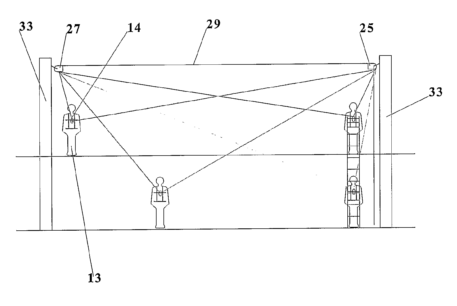
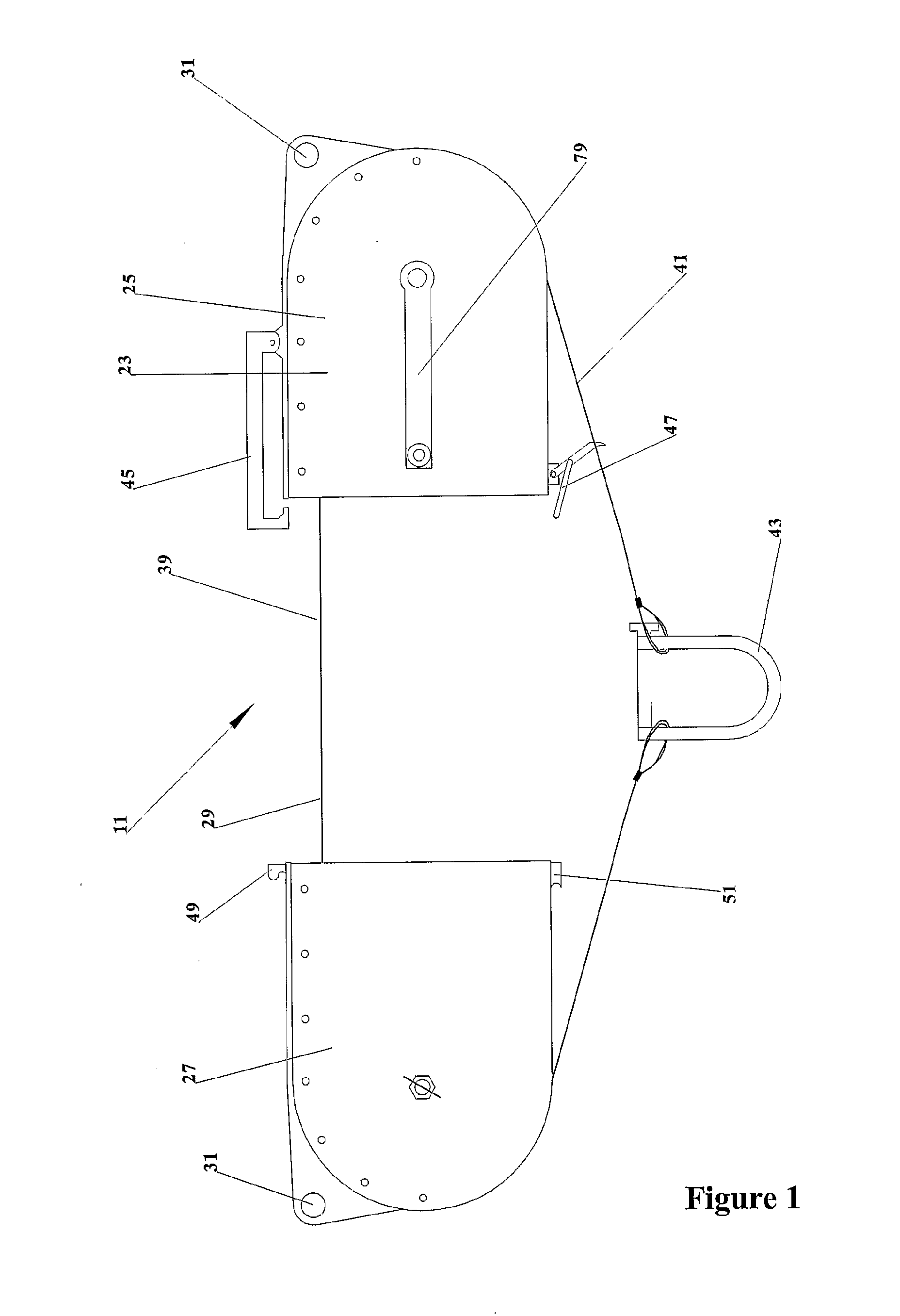
[0073]Shown in FIG. 1 is a safety apparatus 11 according to a As shown in FIG. 10, the safety apparatus 11 may be used to provide a fall restraint for an operator 13 when operating on elevated work platforms.

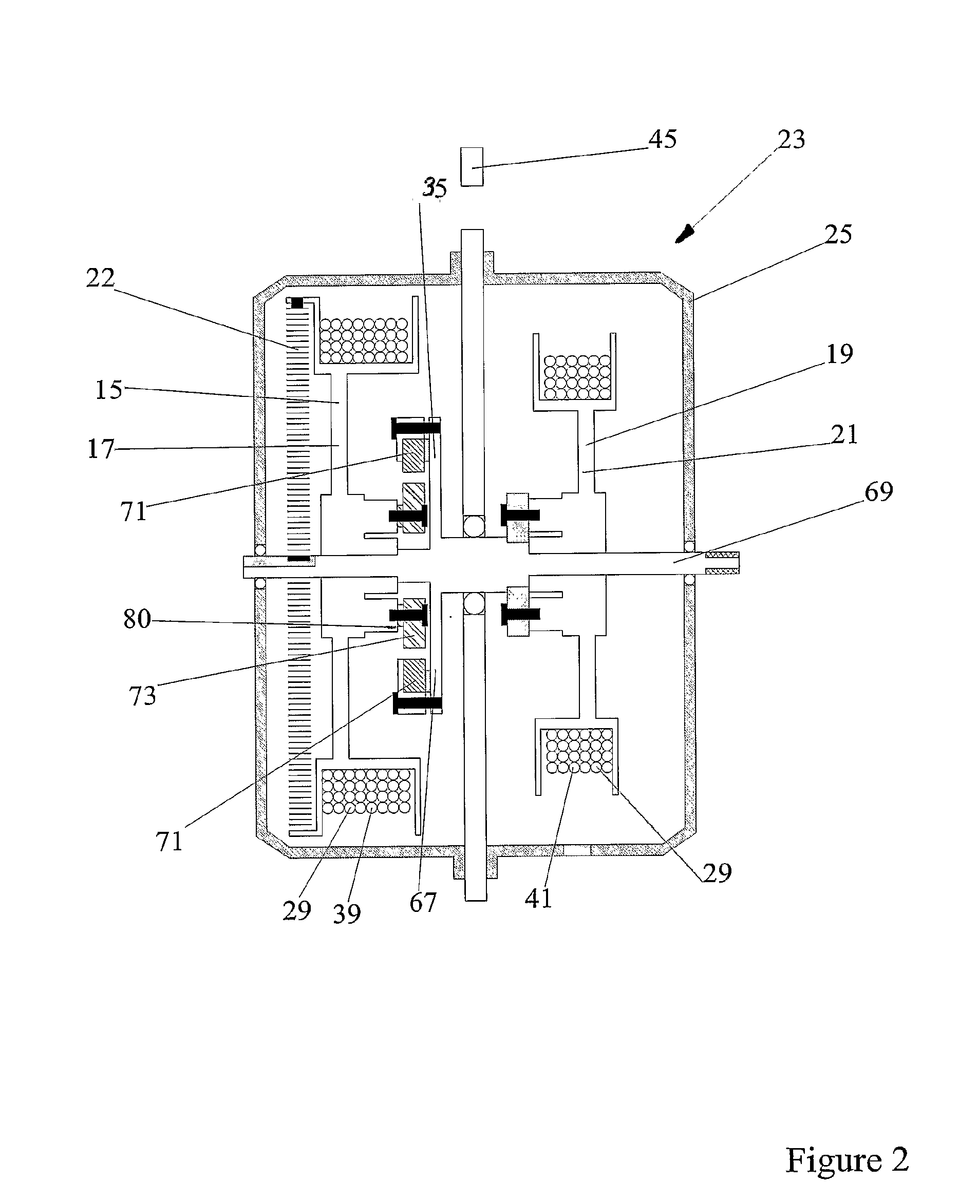
[0074]As best shown in FIGS. 1 and 2, the safety apparatus 11 comprises a first receiving means 15 in the form of a first spool 17 and a second receiving means 19 in the form of a second spool 21. The first spool 17 and second spool 21 are rotatably and coaxially mounted in a first support structure 23 which is in the form of a first housing 25. The first spool 17 is rotatably mounted on a shaft 69 which is rotatably mounted in the first housing 25. The second spool 21 is fixed to the shaft 69. The first housing 25 has an aperture 31 to releasably secure the first housing 25 to a structure 33, as shown in FIG. 10.

[0075]The safety apparatus 11 comprises a locking device 35 operably movable between a released condition whereby the first spool 17 and second spool 21 can move indep...

second embodiment

[0094]Referring to FIGS. 8 and 9, the second support assembly 27 is in the form of a pulley 53 comprising a wheel 55 rotatably retained in a bracket 57. The pulley 53 also incorporates a braking means 59 in the form of a brake lining 61 and a spring 65. As can be seen in FIG. 9, the wheel 55 is mounted in slotted apertures 63 and is biased towards the rear of the slotted apertures 63 by the spring 65. Should the operator 13 fall, the load placed upon the wheel 55 will overcome the biasing force and force the wheel 55 to move towards and engage the brake lining 61, braking the rotation of the wheel 55. This will assist in absorbing some of the impact the operator 13 will experience when the safety apparatus stops the operators 13 descent. The braking means 59 will also assist in preventing lateral movement of the fallen operator 13 towards a central point between the first housing 25 and second support assembly 27.

[0095]In a further embodiment the safety apparatus 11 comprises a com...


PUM


Abstract

A safety apparatus (11) comprising a first housing (25) supporting a first spool (17) and a second spool (21) coaxially mounted and independently rotatable. The safety apparatus (11) also comprises a support line (29) extending from the first spool (17) to the second spool (21) via a second support assembly (27). The safety apparatus (11) also comprises a locking device (35) operably movable between a locked condition wherein the first spool (17) and second spool (21) are locked relative to each other and a released condition wherein the first spool (17) and second spool (21) may rotate independently. The locking device (11) is maintained in a locked condition, locking the first spool (17) relative to the second spool (21), when a load of predetermined value, such as the weight of a fallen operator, is exerted upon the support line (29).

Description

FIELD OF THE INVENTION[0001]This invention relates to a safety apparatus, and, more specifically to a safety apparatus used in the prevention of falls.BACKGROUND ART[0002]In many situations, particularly in the field of construction and building maintenance, an operator may be operating in an environment where he / she is exposed to the danger of falling from an elevated height, which may result in significant injuries.[0003]Many devices have been developed over recent years to prevent or minimize the risk of falling from a work platform. These devices are commonly referred to as fall arresters or fall restraints, and are typically used in combination with some form of harness or belt worn by the operator.[0004]A common form of a fall arrester consists of a single support line, adapted to be secured to an operator's harness, and which is retractably connected to a braking device that is secured to a support structure. With these fall arresters the braking device automatically locks wh...

Claims


Application Information

Patent Timeline
Patent Type & Authority Applications(United States)
IPC IPC(8): A62B35/00A62B1/10A62B35/04E04G21/32
CPCA62B1/10E04G21/3261A62B35/0093
Inventor DOWIE, LEIGH
Owner KSTRONG HLDG UK LTD
Why Eureka
Try Eureka