Electrical connecting cable

a technology of connecting cable and foil shield, which is applied in the direction of electrical equipment, conductors, and coupling device connections, etc., can solve the problems of increasing assembly time, increasing assembly costs, and reducing the service life of the foil shield, so as to achieve high service life, reduce assembly time, and impart a certain flexural stiffness

a technology of connecting cable and foil shield, which is applied in the direction of electrical equipment, conductors, and coupling device connections, etc., can solve the problems of increasing assembly time, increasing assembly costs, and reducing the service life of the foil shield, so as to achieve high service life, reduce assembly time, and impart a certain flexural stiffness

US20120103647A1Inactive Publication Date: 2012-05-03CONINVERS

Image

  • Electrical connecting cable
  • Electrical connecting cable

Examples


Embodiment Construction

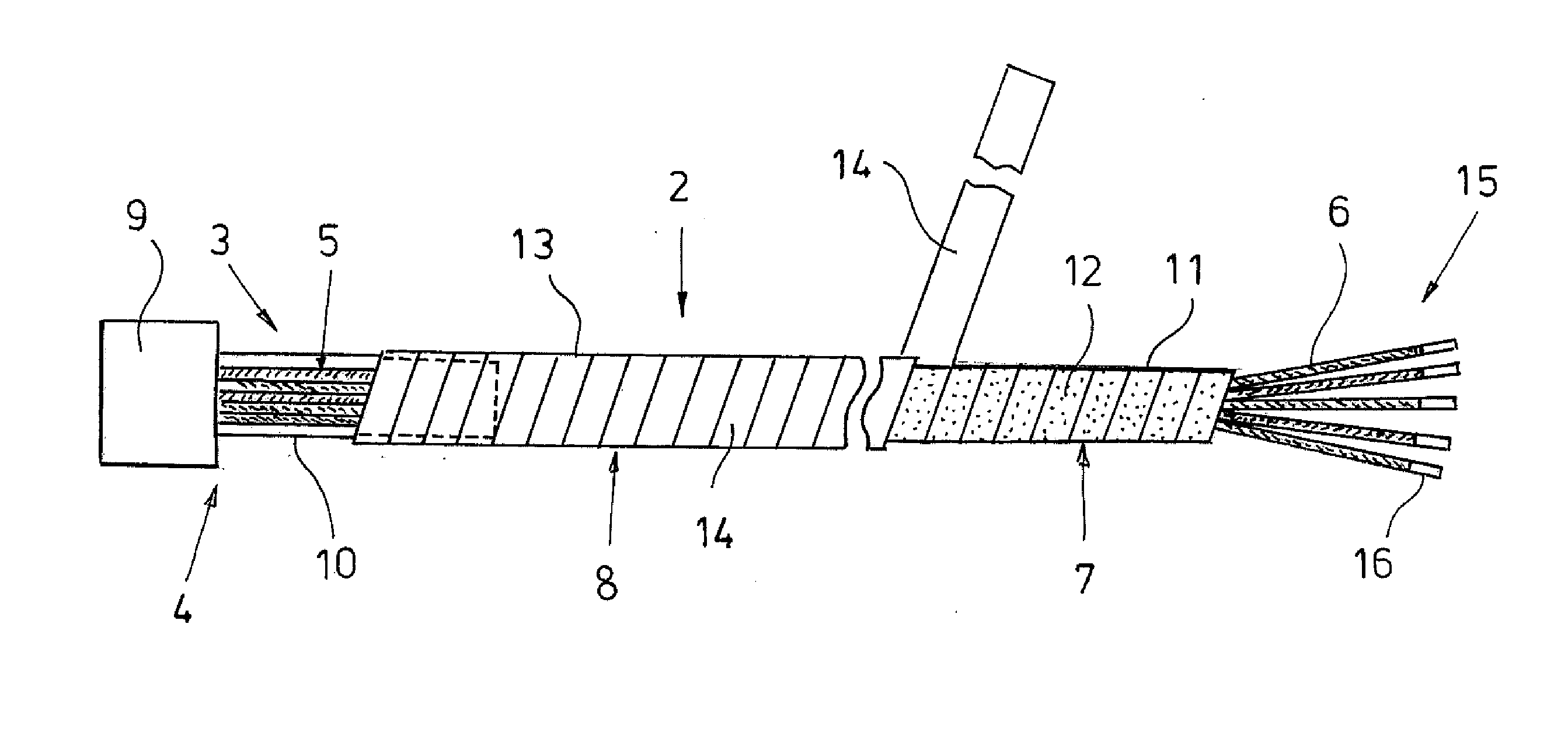
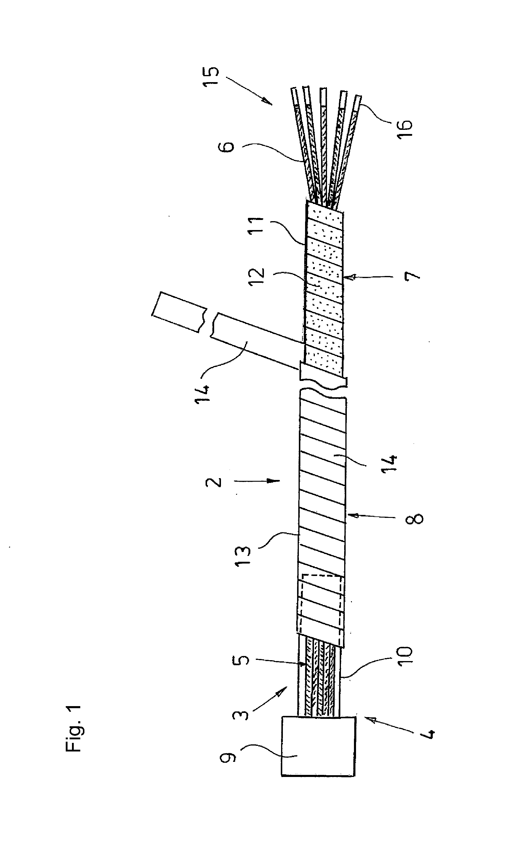
[0018]The drawing shows the electrical connecting cable 1 according to the invention with a flexible electrical cable 2 and a plug connector 4 arranged at a first end 3 of the cable 2 in an extended state. However, since the cable 2 has limited flexural stiffness, it can be routed as desired, in principle. The cable 2 comprises a bundle of conductors 5 of insulated stranded wires 6, a foil shield 7 enclosing the bundle of conductors 5, and a protective sheath 8 encasing the foil shield 7 and serving as outer surface of the cable 2. As plug connector housing 9, the plug connector 4 comprises a round metallic housing holding insulated contacts (not shown) and a shield sleeve that is molded onto the round housing 9 and with which the stranded wires 6 and the foil shield 7 are connected in an electrically conductive way.

[0019]The foil shield 7 is formed by a plurality of consecutive windings 11 of a shield tape 12, and the protective sheath 8 is formed by a number of windings 13 of a sh...


PUM


Abstract

An electrical connecting cable with a flexible electrical cable and with at least one electrical plug connector at one end of the cable, with the electrical cable including a bundle of conductors consisting of insulated stranded wires, a foil shield enclosing the bundle of conductors, and a protective sheath encasing the foil shield and serving as the outer surface of the cable. The plug connector includes a metallic plug connector housing, preferably a round housing, holding insulated contacts and a molded-on shield sleeve with which the stranded wires and the foil shield are connected in an electrically conductive manner. The foil shield includes at least one electrically conductive shield tape and the protective sheath includes at least one electrically non-conductive sheath tape that are both wrapped at an angle spiral-like with a lateral overlap along the stranded wires around the bundle of conductors and the shield sleeve.

Description

CROSS-REFERENCE TO RELATED APPLICATION[0001]The present application claims priority under 35 USC §119 to German Patent Application No. 20 2010 014 872.3 filed Nov. 2, 2010, the entire disclosure of which is incorporated herein by reference.TECHNICAL FIELD OF THE INVENTION[0002]The invention relates to an electrical connecting cable with a flexible electrical cable and with at least one electrical plug connector at one end of the cable, with the electrical cable including a bundle of conductors including insulated stranded wires, a foil shield enclosing the bundle of conductors, and a protective sheath encasing the foil shield and serving as the outer surface of the cable, and with the plug connector including a metallic plug connector housing holding insulated contacts and a molded-on shield sleeve with which the stranded wires and the foil shield are connected in an electrically conductive manner.DESCRIPTION OF THE RELATED ART[0003]Cables with at least one shielded plug connector a...

Claims


Application Information

Patent Timeline
03 May 2012
Publication
US20120103647A1
IPC
H05K9/00
CPC
H01B7/1855; H01R43/28; H01R24/56; H01B11/1025
Inventors
FREY, MICHAEL