Leakage radiation shielding arrangement for a rotary piston x-ray radiator

a technology of leakage radiation shielding and rotary pistons, which is applied in the direction of nuclear engineering, nuclear elements, nuclear engineering problems, etc., can solve the problem of relatively heavy vacuum chambers, and achieve the effect of sufficient shielding against leakage x-ray radiation

a technology of leakage radiation shielding and rotary pistons, which is applied in the direction of nuclear engineering, nuclear elements, nuclear engineering problems, etc., can solve the problem of relatively heavy vacuum chambers, and achieve the effect of sufficient shielding against leakage x-ray radiation

US7382865B2Inactive Publication Date: 2008-06-03SIEMENS AG

Image

  • Leakage radiation shielding arrangement for a rotary piston x-ray radiator
  • Leakage radiation shielding arrangement for a rotary piston x-ray radiator
  • Leakage radiation shielding arrangement for a rotary piston x-ray radiator

Examples


Embodiment Construction

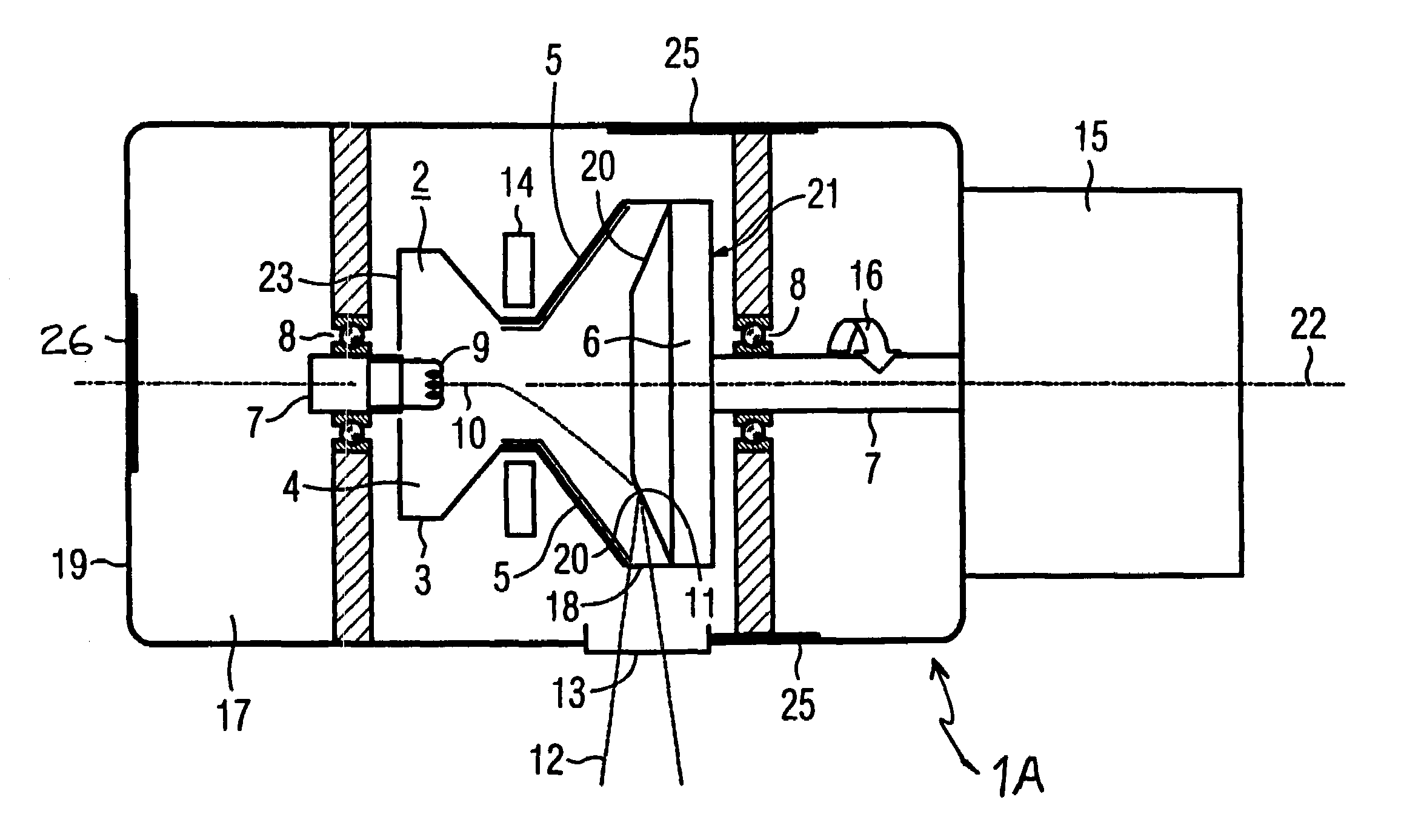
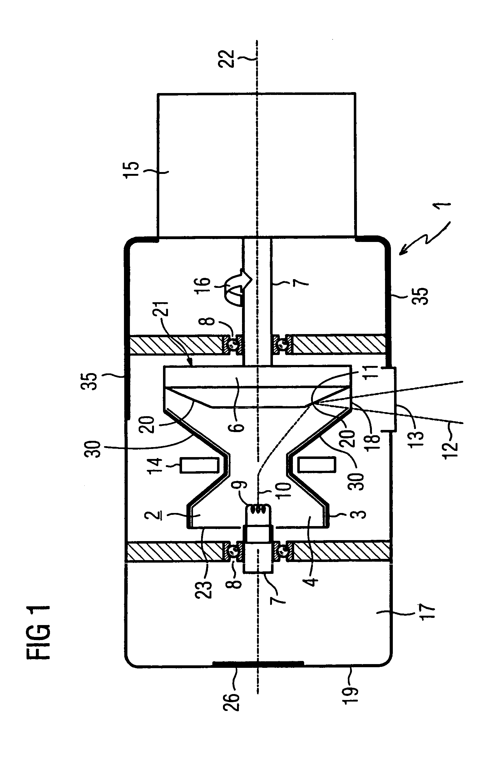
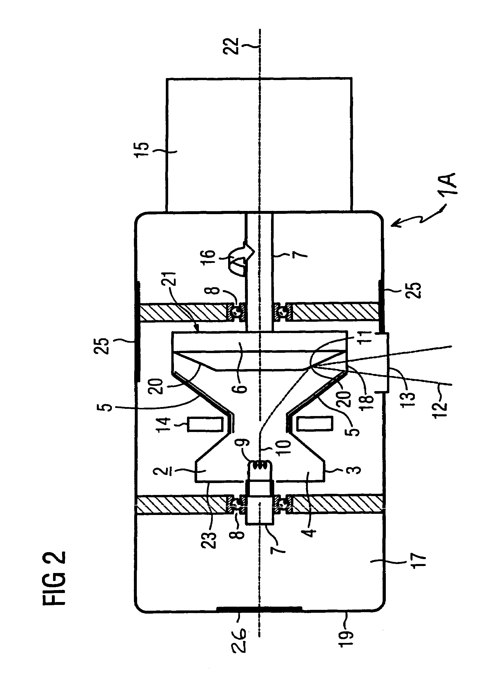
[0014]The inventive rotary piston x-ray radiator 1 shown in FIG. 1 has a rotary piston x-ray tube 2 surrounded by an essentially rotationally-symmetrical vacuum housing 3. The rotary piston x-ray tube 2 has a vacuum 4 inside its vacuum housing 3 and is supported in a radiator housing 19 filled with a cooling medium (such as, for example, insulating oil 17) such that it can rotate on bearings via a shaft 7 around a rotation axis 22, and is driven by an actuator 15 in the rotation direction 16. A base wall of the rotary piston x-ray tube 2 is formed by a rotationally-symmetrical, plate-shaped rotary anode 6 that is permanently connected with the vacuum housing 3 and thus rotates with it. A side of the rotary anode 6 provided with a target 20 is arranged in the vacuum 4 of the vacuum housing 3 and an anode underside 21 of the rotary anode 6 is arranged in the insulating oil 17 of the radiator housing 19.

[0015]A cathode 9 that emits an electron beam 10 is located on the front side 23 of...


PUM


Abstract

For reducing of the weight of leakage x-ray radiation shielding for a rotary piston x-ray tube that rotates in a cooling medium in a radiator housing of an x-ray radiator, the rotary piston x-ray tube having a rotary anode and a cathode fixedly connected with the vacuum housing thereof, the vacuum housing has at least one first region of a total shielding and the radiator housing has at least a second region of the total shielding. Only the respective regions of the vacuum housing and the radiator housing has that are irradiated by the leakage x-ray radiation are provided with shielding.

Description

BACKGROUND OF THE INVENTION[0001]1. Field of the Invention[0002]The present invention relates to rotary piston x-ray radiators, and in particular to a leakage radiation shielding arrangement for such an x-ray radiator.[0003]2. Description of the Prior Art[0004]Rotary piston x-ray radiators, particularly for use in medical apparatuses, must be shielded corresponding to regulatory requirements. In the known x-ray radiator described in DE 196 12 698 C1, for this purpose the radiator housing is designed as a radiation protection housing in order to shield against escaping leakage x-ray radiation, in addition to allowing the usable radiation to exit the housing that is necessary for the actual exposure of a subject to be examined. Moreover, for rotary piston x-ray radiators it is known to apply a material that significantly attenuates the x-ray radiation (such as, for example, lead) on the inside of the x-ray radiator housing in the regions to be shielded.[0005]An x-ray radiator with a c...

Claims


Application Information

Patent Timeline
03 Jun 2008
Publication
US7382865B2
IPC
H01J35/10
CPC
G21F3/00; H01J35/305; G21Y2002/301; G21Y2002/302; G21Y2004/30
Inventors
DEUTSCHER, THOMAS; KUTSCHERA, WOLFGANG