
Electrical connecting cable

a technology of connecting cable and foil shield, which is applied in the direction of electrical equipment, conductors, and coupling device connections, etc., can solve the problems of increasing assembly time, increasing assembly costs, and reducing the service life of the foil shield, so as to achieve high service life, reduce assembly time, and impart a certain flexural stiffness

Inactive Publication Date: 2014-04-22
CONINVERS
View PDF13 Cites 6 Cited by
  • Summary
  • Abstract
  • Description
  • Claims
  • Application Information

AI Technical Summary

Benefits of technology

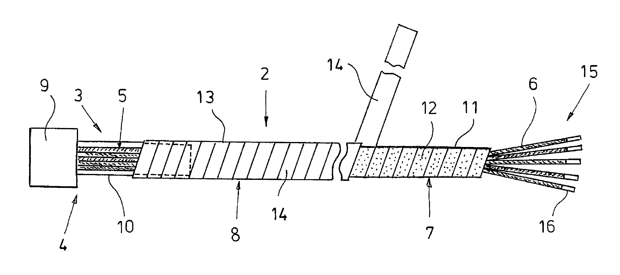
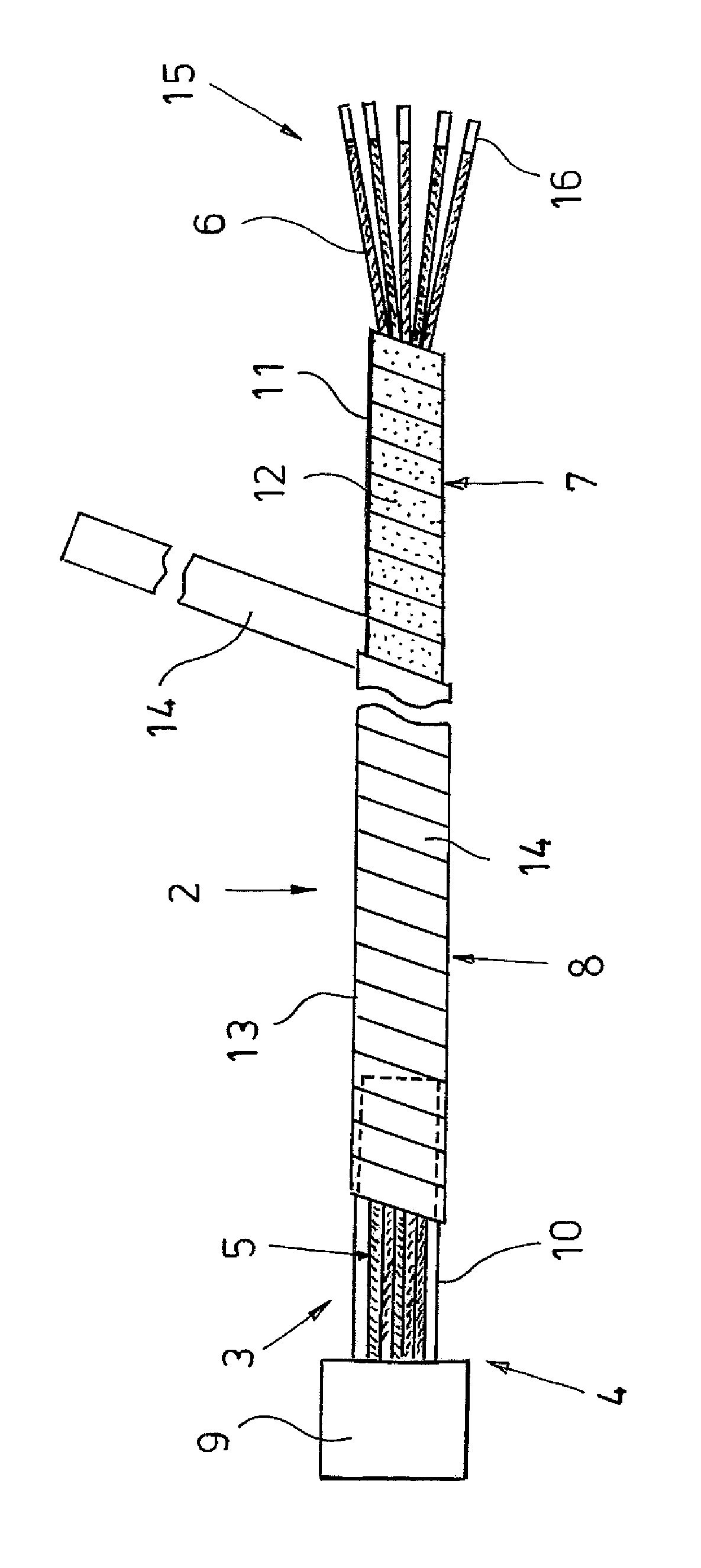
[0010]The shield tape may include a single metal, for example aluminum, a metal composite, for example galvanized copper, or a plastic-and-metal laminate, and is wrapped spiral-like along the stranded wires around the bundle of conductors and around the shield sleeve. In order to ensure sufficient flexibility of the connecting cable, the edges of the shield tape preferably overlap narrowly from one turn to the next. In this way, not only the electrical cable but also the plug connector are shielded sufficiently, especially at the transition between the bundle of conductors and its metallic housing. The shielding produced in this way essentially prevents a signal loss, interference through reception of outside signals, and interference with the environment due to emission of signals to the outside. A 100% shielding of the stranded wires and of the electrical contacts connected with the stranded wires is achieved.
[0011]In general, the electrical connecting cable with the plug connector at one end of the electrical cable may include at its other end, i.e. the end of the electrical cable opposite the plug connector, either free stranded wire ends with or without attached contact elements, an unshielded group plug of any type, or a shieldable second plug connector of preferably similar design as the first plug connector. It is clear that in the case of two plug connectors of shieldable design, the cable shield and the protective sheath that are formed by the wrappings of the shield tape and of the sheath tape, respectively, each overlap the shield sleeves of the two metallic round housings. In each case, the foil shield contacts the at least one metallic round housing at the shield sleeve with low electrical contact resistance and forms a hose-like foil shield composed of the windings of the shield tape. The protective sheath of the connecting cable that is wound by the sheath tape forms a hose-like protective jacket that protects the foil shield against damage and electrical contact from outside. Also, the protective sheath compresses the bundle of conductors with the foil shield in the area of the stranded wires and the foil shield in the area of the shield sleeve that is molded onto the metallic round housing.
[0014]For an efficient production and a low flexural stiffness of the proposed electrical connecting cable it proved to be advantageous to wind the shield tape and the sheath tape in the same direction. It is also advantageous to start the winding at the same place. It proved to be especially advantageous to wind the shield tape and the sheath tape spiral-like, starting at the shield sleeve. By starting the winding of the shield tape at the shield sleeve, each successive turn overlaps the previous one so that the shield tape cannot become detached from the shield sleeve unintentionally. The same is true for the sheath tape that protects the windings of the foil shield and also positively prevents a detachment of the foil shield from the shield sleeve especially in the area of the shield sleeve. In the area of transition between the shield tape and the shield sleeve, the sheath tape acts as bending protection that can be further improved in this area by wrapping the sheath tape multiple times around the foil shield in the area of transition between the shield tape and the shield sleeve.

Problems solved by technology

When conventional fixed-length cables are used, the attachment of the foil shield to common plug connectors is a costly problem.
In particular, the shielding that is often glued to the insulation of the stranded wires is difficult to cut without damaging the insulation of the stranded wires.
This increases the time required for the assembly, and therefore also the assembly costs.
Furthermore, the production of the electrical connecting cable is generally a time-consuming process and limits the rate at which the cable can be produced.
Besides the not fully-automated production process, the relatively high individual cost of the ready-made cable is another obstacle when it comes to providing a connecting cable at reasonable cost.

Method used


Image

  • Electrical connecting cable
  • Electrical connecting cable

Examples


Embodiment Construction

[0018]The drawing shows the electrical connecting cable 1 according to the invention with a flexible electrical cable 2 and a plug connector 4 arranged at a first end 3 of the cable 2 in an extended state. However, since the cable 2 has limited flexural stiffness, it can be routed as desired, in principle. The cable 2 comprises a bundle of conductors 5 of insulated stranded wires 6, a foil shield 7 enclosing the bundle of conductors 5, and a protective sheath 8 encasing the foil shield 7 and serving as outer surface of the cable 2. As plug connector housing 9, the plug connector 4 comprises a round metallic housing holding insulated contacts (not shown) and a shield sleeve that is molded onto the round housing 9 and with which the stranded wires 6 and the foil shield 7 are connected in an electrically conductive way.

[0019]The foil shield 7 is formed by a plurality of consecutive windings 11 of a shield tape 12, and the protective sheath 8 is formed by a number of windings 13 of a sh...


PUM

PropertyMeasurementUnit
flexibleaaaaaaaaaa
electrically conductiveaaaaaaaaaa
lengthaaaaaaaaaa

Abstract

An electrical connecting cable with a flexible electrical cable and with at least one electrical plug connector at one end of the cable, with the electrical cable including a bundle of conductors consisting of insulated stranded wires, a foil shield enclosing the bundle of conductors, and a protective sheath encasing the foil shield and serving as the outer surface of the cable. The plug connector includes a metallic plug connector housing, preferably a round housing, holding insulated contacts and a molded-on shield sleeve with which the stranded wires and the foil shield are connected in an electrically conductive manner. The foil shield includes at least one electrically conductive shield tape and the protective sheath includes at least one electrically non-conductive sheath tape that are both wrapped at an angle spiral-like with a lateral overlap along the stranded wires around the bundle of conductors and the shield sleeve.

Description

CROSS-REFERENCE TO RELATED APPLICATION[0001]The present application claims priority under 35 USC §119 to German Patent Application No. 20 2010 014 872.3 filed Nov. 2, 2010, the entire disclosure of which is incorporated herein by reference.TECHNICAL FIELD OF THE INVENTION[0002]The invention relates to an electrical connecting cable with a flexible electrical cable and with at least one electrical plug connector at one end of the cable, with the electrical cable including a bundle of conductors including insulated stranded wires, a foil shield enclosing the bundle of conductors, and a protective sheath encasing the foil shield and serving as the outer surface of the cable, and with the plug connector including a metallic plug connector housing holding insulated contacts and a molded-on shield sleeve with which the stranded wires and the foil shield are connected in an electrically conductive manner.DESCRIPTION OF THE RELATED ART[0003]Cables with at least one shielded plug connector a...

Claims


Application Information

Patent Timeline
Patent Type & Authority Patents(United States)
IPC IPC(8): H01B7/00
CPCH01R43/28H01B11/1025H01R24/56H01B7/1855
Inventor FREY, MICHAEL
Owner CONINVERS
Learn More