Pile-Driver Assembly and Method for Driving a Pile Into the Ground

Pending Publication Date: 2022-11-10
IHC HOLLAND NV
View PDF1 Cites 0 Cited by
  • Summary
  • Abstract
  • Description
  • Claims
  • Application Information

AI Technical Summary

Benefits of technology

[0007]This arrangement provides a pile-driver assembly that drives a pile into the ground, in particular larger piles (typically with rims larger than 6 meters in diameter) in an efficient manner. In contrast to known hammer arrangements, in this arrangement there is no hammer enclosed within a casing and actively driven into a pile. Instead, the release of a chamber of fluid, for example water, from a distance away from the pile is utilised to drive the pile into the ground. The arrangement allows the use of a chamber with a much larger mass (particularly when filled with fluid) and the ‘push’ applied by the chamber onto the pile, rather than a driven hammer. Such an arrangement is more subtle and creates less noise then hammer arrangements. The reduction in noise from known arrangements is two-fold. Firstly the peak noise level of each blow is reduced and additionally, the large mass of the chamber is such that fewer impacts are required by the pile-driver and hence the cumulative noise (the number of blows×peak noise per blow).
[0046]Aptly, the method further comprises controllably buffering the force exerted by the chamber on the pile when the pile is controllably driven into the ground. This method step helps enable the assembly to perform the piling operation with a minimum underwater noise generation and therefore, underwater noise propagation.

Problems solved by technology

However, the designs of known pile-drivers have not been well suited for driving large diameter piles into the ground off-shore.
Conventional pile-drivers have been limited in the impact forces that their hammers can apply to the tops of piles.

Method used


Image

  • Pile-Driver Assembly and Method for Driving a Pile Into the Ground
  • Pile-Driver Assembly and Method for Driving a Pile Into the Ground
  • Pile-Driver Assembly and Method for Driving a Pile Into the Ground

Examples


Embodiment Construction

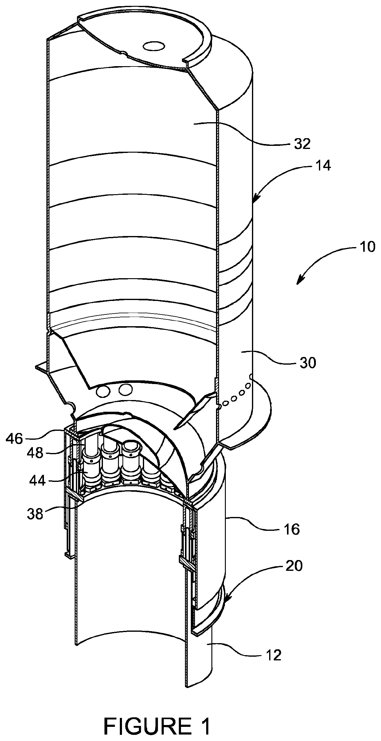
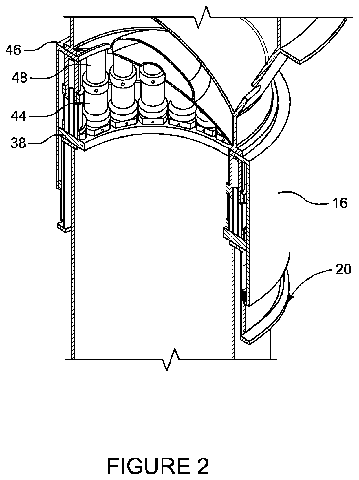
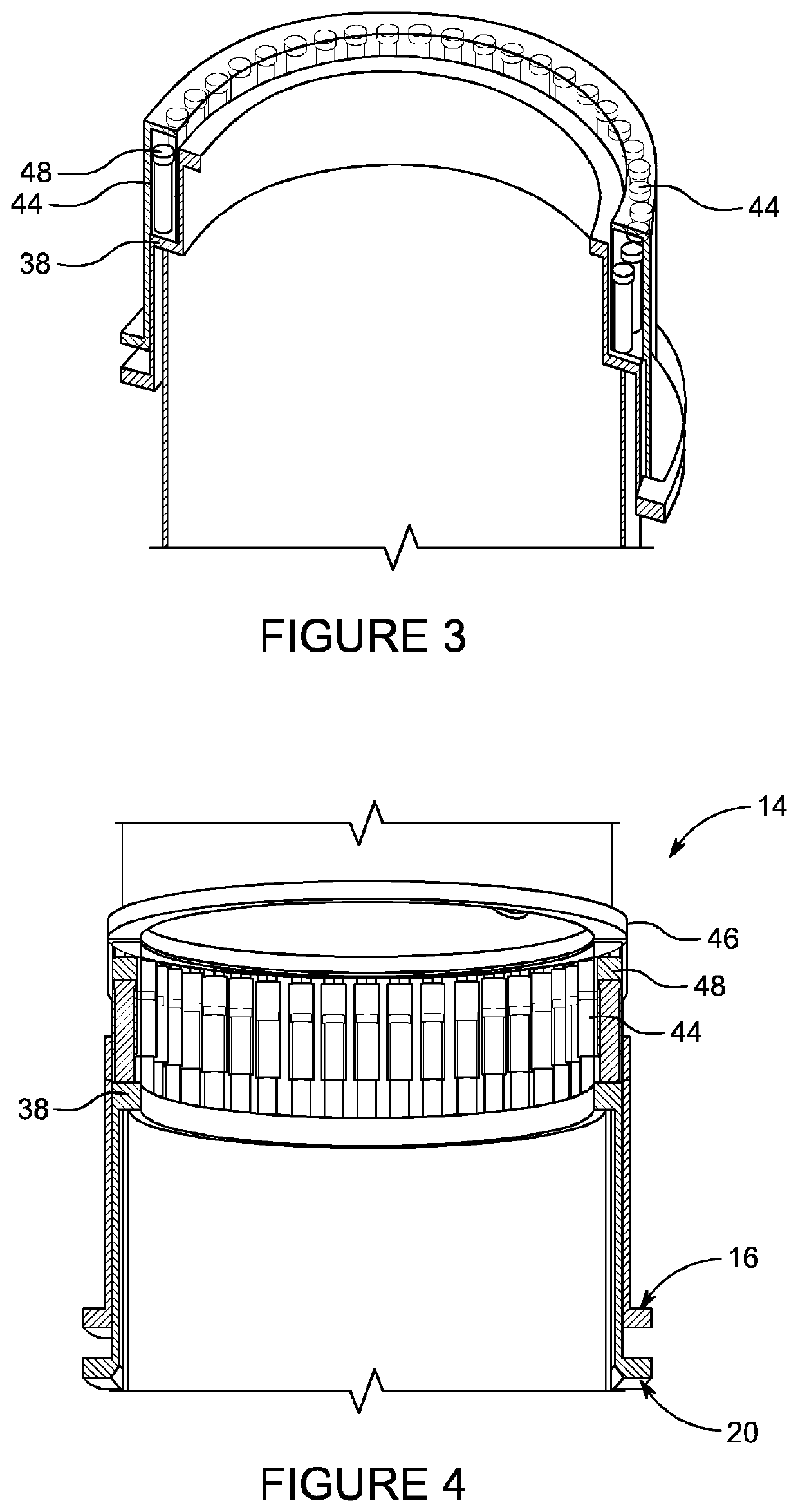
[0061]FIGS. 1 to 5 illustrate an example of a pile-driver assembly 10 for driving a pile 12 into the ground. The pile-driver assembly 10 includes a casing 14 defining a chamber 32. That is, the casing 14 comprises an interior volume (i.e. chamber 32) defined by an outer wall 30. In this example, the casing 14 is substantially cylindrical (i.e. the outer wall 30 of casing 14 is substantially cylindrical). The cylindrical shape of the casing enables easy transportation of the assembly. In addition, the cylindrical shape allows for a good load transfer of the pressure that builds up inside the casing. The internal pressure during impact results in a hoop stress in the wall of the casing. However in other examples casings of different shapes may be used.

[0062]The chamber 32 is configured to house a fluid, for example water. In other words, the chamber provides a generally sealed space configured to house and maintain a volume of fluid therein. The casing 14 may include a valve in a wall...


PUM


Abstract

A pile-driver assembly for driving a pile into the ground, preferably offshore, and a method of driving a pile into the ground using the pile-driver assembly is disclosed. The assembly includes a casing defining a chamber, the chamber being configured to house a fluid. The assembly further includes a positioning element configured to position the casing at or on the pile, wherein at least a portion of the positioning element is positioned between the chamber and the pile. The assembly further includes actuating means, wherein actuation of the actuating means displaces the chamber relative to the positioning element, such that the chamber moves away from the pile, and wherein the actuating means is configured to release the chamber for displacement towards the pile such that a force is exerted by the chamber on the positioning member, to controllably drive the pile into the ground.

Description

TECHNICAL FIELD[0001]The present invention relates to a pile-driver, and more particularly to a pile-driver suitable for offshore operations. The present invention also relates to a method for driving a pile downward into the ground.BACKGROUND TO THE INVENTION[0002]Driving a pile into the ground offshore typically involves dropping a ram or hammer on to the top of the pile from some height via a striker plate. To apply the downward impact forces of the hammer over a larger surface area of the top of the pile and to protect the top of the pile from damage, an impact liner of wood has generally been placed between the underside of the strike plate or anvil and the top of the pile (see DE8900692U1). In order to better protect the strike plate and the top of the pile, the use of pressure gas springs, connected to the strike plate, has also been proposed (see DE8900692U1). In order to protect the hammer and the top of the pile from damage from the direct impact of the hammer on the pile,...

Claims


Application Information

Patent Timeline
Patent Type & Authority Applications(United States)
IPC IPC(8): E02D7/10E02D7/14E02D13/00
CPCE02D7/10E02D7/14E02D13/005E02D2250/0092E02D7/06E02D13/00E02D13/04E02D13/10E02D5/285E02D7/02E02D7/08E02D2250/0061
Inventor WINKES, JASPER STEFAN
Owner IHC HOLLAND NV
Why Eureka
Try Eureka