Digital audio signal coding using a CELP coder and a transform coder

a technology of digital audio signal and transform coder, which is applied in the field of digital coding of audio signals, can solve the problems of more or less suited coding techniques of different types

Inactive Publication Date: 2000-10-17
CISCO TECH INC
View PDF12 Cites 394 Cited by
  • Summary
  • Abstract
  • Description
  • Claims
  • Application Information

AI Technical Summary

Problems solved by technology

However, the differing characteristics of the various types of audio signals has the consequence that different types of coding techniques are more or less suited to certain types of signals.

Method used


Image

  • Digital audio signal coding using a CELP coder and a transform coder
  • Digital audio signal coding using a CELP coder and a transform coder
  • Digital audio signal coding using a CELP coder and a transform coder

Examples


Embodiment Construction

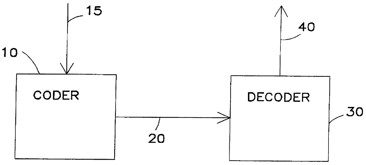
FIG. 1 shows a generalized view of an audio signal coding system. Coder 10 receives an incoming digitized audio signal 15 and generates from it a coded signal. This coded signal is sent over transmission channel 20 to decoder 30 wherein an output signal 40 is constructed which resembles the input signal in relevant aspects as closely as is necessary for the particular application concerned. Transmission channel 20 may take a wide variety of forms including wired and wireless communication channels and various types of storage devices. Typically, transmission channel 20 has a limited bandwidth or storage capacity which constrains the bit rate, ie the number of bits required per unit time of audio signal, for the coded signal.

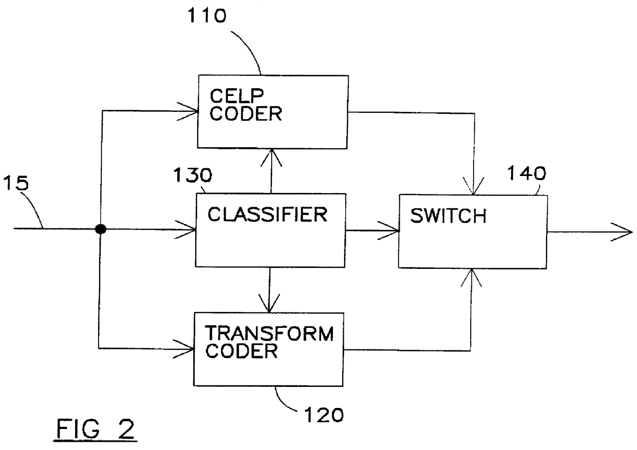
FIG. 2 is a schematic block diagram of audio signal coder 10 in the preferred embodiment of the invention. Input signal 15 is fed in to speech state coder 110, music state coder 120 and classifier device 130. In this embodiment speech state coder 110 is a Codeboo...


PUM


Abstract

Apparatus is described for digitally encoding an input audio signal for storage or transmission. A distinguishing parameter is measure from the input signal. It is determined from the measured distinguishing parameter whether the input signal contains an audio signal of a first type or a second type. First and second coders are provided for digitally encoding the input signal using first and second coding methods respectively and a switching arrangement directs, at any particular time, the generation of an output signal by encoding the input signal using either the first or second coders according to whether the input signal contains an audio signal of the first type or the second type at that time. A method for adaptively switching between transform audio coder and CELP coder, is presented. In a preferred embodiment, the method makes use of the superior performance of CELP coders for speech signal coding, while enjoying the benefits of transform coder for other audio signals. The combined coder is designed to handle both speech and music and achieve an improved quality.

Description

The present invention is related to the below-listed copending applications filed on the same date and commonly assigned to the assignee of this invention: FR9 97 010.1. Field of the InventionThis invention relates to digital coding of audio signals and, more particularly, to an improved wideband coding technique suitable, for example, for audio signals which include a mixture of music and speech.2. Background DescriptionThe need for low bitrate and low delay audio coding, such as is required for video conferencing over modern digital data communications networks, has required the development of new and more efficient schemes for audio signal coding.However, the differing characteristics of the various types of audio signals has the consequence that different types of coding techniques are more or less suited to certain types of signals. For example, transform coding is one of the best known techniques for high quality audio signal coding in low bitrates. On the other hand, speech s...

Claims


Application Information

Patent Timeline
Patent Type & Authority Patents(United States)
IPC IPC(8): G10L19/14G10L19/00G10L19/04G10L19/02G10L19/18
CPCG10L19/18G10L19/0212G10L19/04
Inventor COHEN, GILADCOHEN, YOSSEFHOFFMAN, DORONKRUPNIK, HAGAISATT, AHARON
Owner CISCO TECH INC
Why Eureka
Try Eureka