Valve assembly

a valve assembly and valve body technology, applied in water installations, thin material processing, construction, etc., can solve the problems of chemical loss, health risk to both the operator and the surrounding area, and none of these devices efficiently meet these concerns, so as to reduce chemical loss at the valve connection, increase the safety of operators, and reduce the effect of chemical loss

Inactive Publication Date: 2000-10-24
KAYLYNN
View PDF6 Cites 70 Cited by
  • Summary
  • Abstract
  • Description
  • Claims
  • Application Information

AI Technical Summary

Problems solved by technology

During tank filling processes when toxic or hazardous chemicals are being transferred into smaller cylinders, chemical loss occurs when the cylinders are connected to and disconnected from the manifold because the chemical sometimes remains in the lines that connect the manifold and the cylinders and leaks to the environment.
This chemical loss is a health risk to both the operator and to the surrounding areas.
Several devices have been developed in the past, but none of these devices efficiently meets these concerns.

Method used


Image

  • Valve assembly
  • Valve assembly
  • Valve assembly

Examples


Embodiment Construction

Illustrations of preferred construction, design, and methods of operation of the invention are set forth below with specific references to the Figure. However, it is not the intention of the inventor that the scope of his invention be limited to these preferred embodiments.

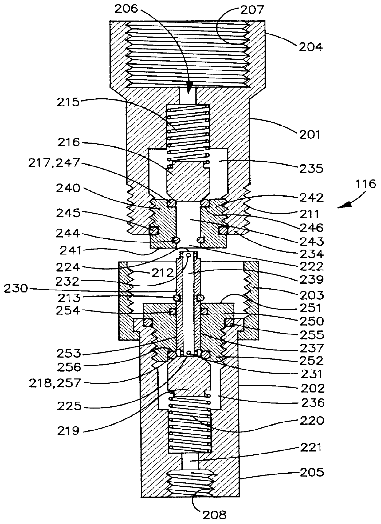
As shown in FIG. 1a, valve assembly 116 comprises an inlet valve 201 connectable to an outlet valve 202. Valves 201, 202 may be connected directly to each other using threaded or other connections, such as a coupler 203. Coupler 203 is rotatably mounted to outlet valve 202 using a shoulder and snap ring assembly, or any other suitable assembly for connecting coupler 203 to outlet valve 202. Each valve 201, 202 is constructed similar to a spring-loaded ball or plug check valve having a plug or ball positioned within the bores 235, 236 of respective valves 201, 202.

Inlet valve 201 is configured with inlet port 206 and an outlet port 222 with bore 235 extending therebetween. First end 204 of inlet valve 201 is config...


PUM


Abstract

A valve assembly used to minimize chemical loss during the transfer of chemicals from one container to another is disclosed herein. The valve assembly minimizes chlorine or other process material loss to the environment by sealing the manifold and the cylinder to be filled from the environment while the valve assembly is connected or disconnected. The valve assembly includes an inlet valve connectable to an outlet valve, the inlet valve comprising a first plug positioned in a bore extending between an inlet and outlet port and a transfer tube engaging a bore of a first insert positionable within the bore of the inlet valve. The outlet valve comprises a second plug positioned in a bore extending between an inlet and outlet port and second insert positionable within the bore of the outlet valve. The transfer tube has a first and second end configured to be insertable at least partially within respective bores of the first and second inserts, the first and second ends each having at least one port. A bore extends through the transfer tube to allow fluid communication between the first and second ends.

Description

1. Field of the InventionThis invention relates to a valve assembly for filling gas cylinders, more particularly a valve assembly that reduces the amount of gas wasted during the filling process.2. Prior ArtDuring tank filling processes when toxic or hazardous chemicals are being transferred into smaller cylinders, chemical loss occurs when the cylinders are connected to and disconnected from the manifold because the chemical sometimes remains in the lines that connect the manifold and the cylinders and leaks to the environment. This chemical loss is a health risk to both the operator and to the surrounding areas. Thus, a need exists for a valve connection that can minimize this chemical loss.Several devices have been developed in the past, but none of these devices efficiently meets these concerns. An example of a prior art device is shown in U.S. Pat. No. 5,379,793. A need exists for an improved valve assembly that can decrease chemical loss every time a tank is filled while at th...

Claims


Application Information

Patent Timeline
Patent Type & Authority Patents(United States)
IPC IPC(8): F16L29/04F16L29/00
CPCF16L29/04Y10T137/87949Y10T137/87957
Inventor POWELL, JONATHAN S.MODESETT, DEAN
Owner KAYLYNN
Why Eureka
Try Eureka