Measurement of pain

a technology of pain measurement and measuring instruments, applied in the field of measuring instruments, can solve the problems of complicating the complicating the quick and exact diagnosis of a person's ailment or injury, and the doctor cannot objectively verify the pain value given by the patien

Inactive Publication Date: 2000-11-14
CEFAR MATCHER
View PDF14 Cites 43 Cited by
  • Summary
  • Abstract
  • Description
  • Claims
  • Application Information

AI Technical Summary

Benefits of technology

Yet another object of the present invention is to provide a measurement value of pain which is relevant for comparison between different patients.
A further object of the present invention is to provide a portable, very easy to use, measuring instrument for the measurement of pain.
Yet a further object of the present invention is to allow the doctor, the physiotherapist etc. to feel and sense the patient's pain, which has a psychological significance that may entail a shortened time for medical care of the patient, as the patient feels he has been understood.

Problems solved by technology

However, this creates a significant problem for the medical staff, depending upon different persons experiencing, and therefore describing, their pain or symptoms in different ways.
The varying descriptions of pain which a diagnostician may be exposed to, complicate a quick and exact diagnosis of a person's ailment or injury.
One problem with this ruler according to FIGS. 1 and 2 is that the patient must consciously think about and evaluate where to place his finger on the ruler, between the values no sensation of pain and unbearable sensation of pain, as shown in FIG. 2.
Another problem with the ruler according to FIGS. 1 and 2 is that the doctor cannot objectively verify the pain value given by the patient; the patient may e.g. lie about his sensation of pain and place his finger at the same pain value at different measurement occasions.
A further problem with the ruler according to the FIGS. 1 and 2 is that different persons sense pain in different ways.
The documents found do not solve the problems mentioned above.

Method used


Image

  • Measurement of pain
  • Measurement of pain
  • Measurement of pain

Examples


first embodiment

In the following, each of the embodiments mentioned according to FIGS. 3-10 will be discussed. the invention will be described in more detail, as this embodiment will also describe the idea of the invention by means of an example.

The other embodiments are based on the same inventive idea.

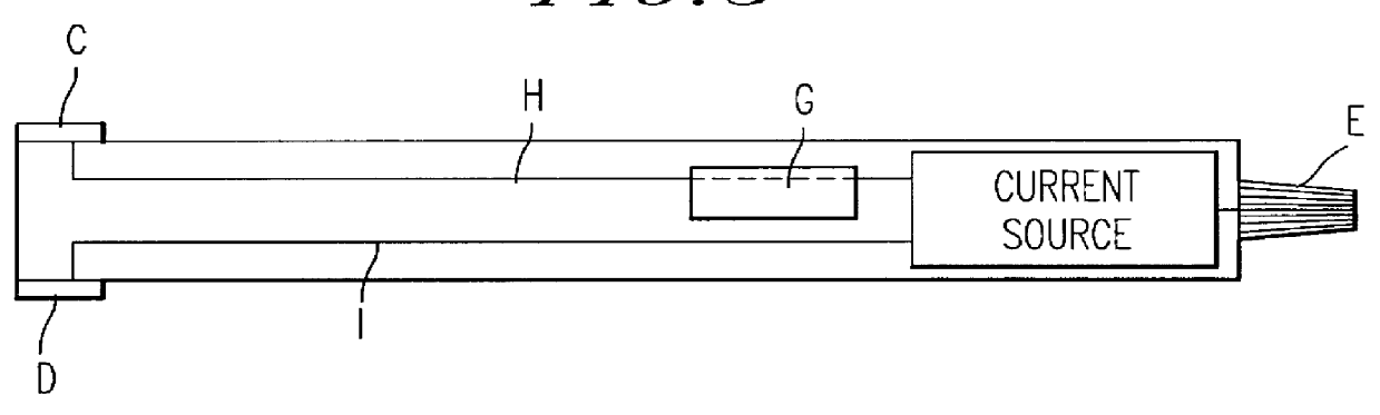
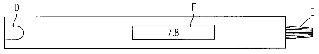
Referring now to FIGS. 3 and 4, two electrodes C and D are attached, one on each side, at one end of the measuring instrument. The electrodes are connected by wires I and H to a current source, where the current is controlled by a control knob E.

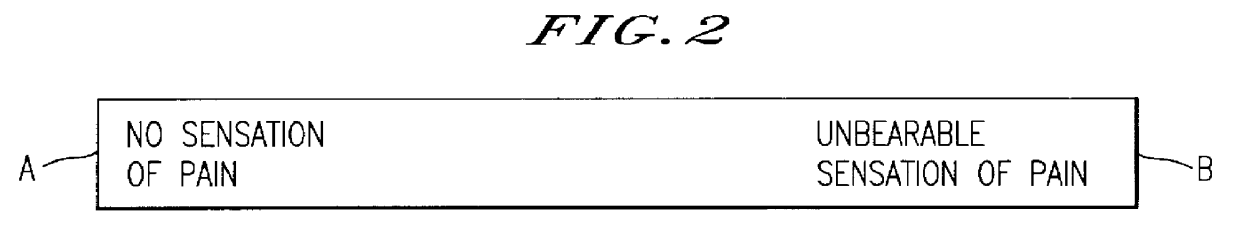
At one side of the measuring instrument there is a display F, capable of showing, e.g. digitally, a value of e.g. 0-10. This value is of course intended for indication, in the same way as before, of a degree of pain sensed, where the value "0" corresponds to a total absence of pain and the value "10" corresponds to an unbearable pain.

Furthermore, there is a memory register G for storage of an arbitrary number of pain readings (0-10).

The present invention wil...

second embodiment

FIG. 5 shows the measuring instrument according to the invention. This embodiment differs from the measuring instrument in FIGS. 3 and 4 only by the current to the electrodes C and D being increased by means of a push-button J.

By depressing this button J, the current is thus increased in an arbitrary, predetermined fashion; for example 50 .mu.A upon each depression.

The FIGS. 6 and 7 show an especially preferred embodiment of the measuring instrument. This embodiment functions in such a way that when e.g. the thumb and the index finger grasp around the electrodes C and D, a current circuit is closed, whereby a current flows from the current source via the wire H and the electrode C through the thumb and the index finger, and back to the current source via the electrode D and the wire I. The current increases automatically by steps of e.g. 50 .mu.A, being controlled by a microprocessor K. Furthermore, the microprocessor may be programmed so as to control the current increase in a line...

fourth embodiment

FIG. 8 shows the measuring instrument. This measuring instrument in principle functions in the same manner as the measuring instrument of FIGS. 6 and 7; the current will increase automatically when the current circuit is closed (i.e. when the electrodes C and D are short-circuited).

This measuring instrument however differs from the earlier described measuring instruments by having its electrodes C and D arranged in such a manner as to be applicable anywhere on the body. This measuring instrument is especially advantageous for use with extremities which are paired, e.g. arms, legs, ears, etc.

Assume for example that a patient has a pain in his left knee. The doctor then applies the electrodes C and D of the measuring instrument according to FIG. 8 onto the patient's right knee, whereupon pain is also induced in this knee. The measuring instrument according to FIG. 8 thus utilises the principle that it is easier for a patient to associate a pain in his left knee with a pain in his righ...


PUM


Abstract

PCT No. PCT / SE96 / 01668 Sec. 371 Date Sep. 21, 1998 Sec. 102(e) Date Sep. 21, 1998 PCT Filed Dec. 18, 1996 PCT Pub. No. WO97 / 24068 PCT Pub. Date Jul. 10, 1997A measuring instrument for the measurement of an existing pain or a feeling of nausea of a patient. The measuring instrument induces pain in an arbitrary body part of said patient, by supplying an electrical current. The measuring instrument provides a current increase into said body part, until said induced pain is experienced by the patient as being as great as the existing pain / nausea. The current is supplied from a current source arranged in the measuring instrument via wires and electrodes, said electrodes being applied onto that part of the body in which pain is to be induced. When the pain induced is experienced to be as great as the existing pain / nausea, the body part is removed from the electrodes, whereupon a pain value is registered and shown on a display.

Description

FIELD OF THE INVENTIONThe present invention relates to a measuring instrument and a method of measuring, by means of said instrument, an existing pain experienced by a patient.DISCUSSION OF THE BACKGROUNDWhen a person in need of medical treatment first comes into contact with a doctor, a physiotherapist, a nurse etc., this person generally tries to describe his pain verbally, so that the medical staff are at least able to make a primary diagnosis of the patient's condition and suggest a suitable treatment. However, this creates a significant problem for the medical staff, depending upon different persons experiencing, and therefore describing, their pain or symptoms in different ways. One person may e.g. be more resistant to pain than others. Another person may e.g. have become used to his pain after a certain period of time and may therefore describe his / her pain in milder terms than he / she would have done if the pain had arisen recently. The varying descriptions of pain which a di...

Claims


Application Information

Patent Timeline
Patent Type & Authority Patents(United States)
IPC IPC(8): A61B5/103A61B5/16
CPCA61B5/4824
Inventor LASEROW, KAY
Owner CEFAR MATCHER
Why Eureka
Try Eureka