Directive antenna for mobile telephones

a direct-type antenna and mobile telephone technology, applied in the direction of antennas, antenna details, simultaneous aerial operations, etc., can solve the problem of significant reduction of the performance of many prior-art antennas

Inactive Publication Date: 2000-11-14
NEC CORP
View PDF1 Cites 96 Cited by
  • Summary
  • Abstract
  • Description
  • Claims
  • Application Information

AI Technical Summary

Problems solved by technology

The performance of many prior art antennas is significantly red

Method used


Image

  • Directive antenna for mobile telephones
  • Directive antenna for mobile telephones
  • Directive antenna for mobile telephones

Examples


Embodiment Construction

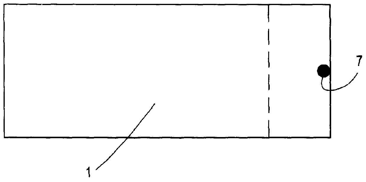
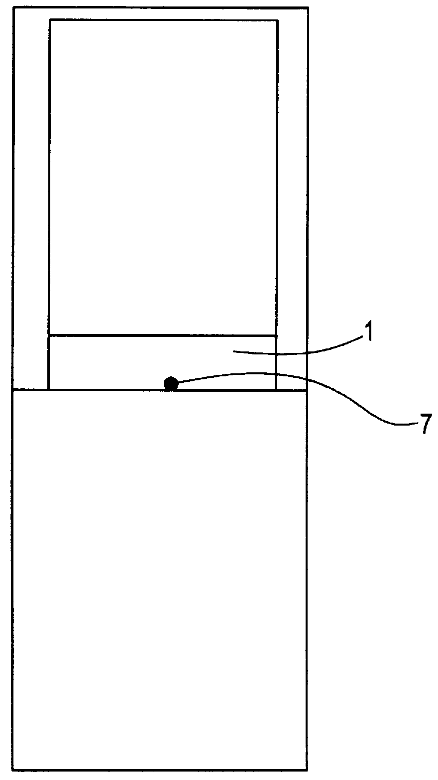
In this example, a foldable telephone as illustrated in FIGS. 2 and 3 is operable in two network bands, the two network bands being GSM 900 operating in the band 890 to 960 MHz and DCS 1800 operating in the band 1710 to 1880 MHz.

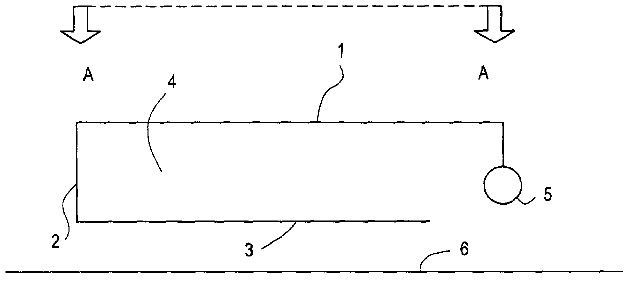
With reference to the figures, in which the parts illustrated are given the same numbers throughout, a simplified cross sectional view of the antenna is shown in FIGS. 1 and 2. The antenna comprises a single rectangular sheet of copper which has been bent firstly to produce a first patch antenna section 1 and secondly to produce a second patch antenna section 3, sections 1 and 3 being joined by and contiguous with section 2. Section 2 is an integral part of the copper sheet and maintains the two sections 1 and 3 in substantially parallel spaced relationship with each other. An air gap 4 exists between sections 1 and 3. Other low absorption insulators may be used in place of air gap 4 and may be selected from a range of such insulators well known in the art. ...


PUM


Abstract

The antenna comprises a single rectangular sheet of copper which has been bent firstly to produce a first patch antenna section 1 and secondly to produce a second patch antenna section 3, sections 1 and 3 being joined by and contiguous with section 2. Section 2 is an integral part of the copper sheet and maintains the two sections 1 and 3 in substantially parallel spaced relationship with each other. An air gap 4 exists between sections 1 and 3. Other low absorption insulators may be used in place of air gap 4 and may be selected from a range of such insulators well known in the art. The antenna is backed by a ground plane 6 and is fed by means of a coaxial connector 5 to the distal edge of the larger patch at 7 where excitation of the antenna is effected.

Description

1. Field of the InventionThis invention relates to antennas for use with radio transceivers and in particular for use with mobile telephones.2. Description of the Related ArtThe design of antennas for radio transmitter / receivers (transceivers) capable of operation in more than one frequency band is constrained by the market demand continually to reduce the overall size of radio transceivers. The term "dual mode" is generally used to describe a radio transceiver capable of operation in two separate frequency bands and that description will be used herein.An antenna for a foldable or "flip" telephone will need to be especially compact while still being capable of providing satisfactory performance. Simplified illustrations of a foldable phone are given in the accompanying figures. Foldable phones as illustrated in the figures usually comprise two housings of approximately the same size.When such a telephone is in the closed position, performance of the antenna must also be sufficient ...

Claims


Application Information

Patent Timeline
IPC IPC(8): H01Q9/04H01Q1/24H01Q5/00H01Q13/08H01Q5/357
CPCH01Q1/243H01Q5/357H01Q9/0414H01Q1/245
Inventor IVRISSIMTZIS, LEONIDASWALDRON, RUPERT JAMES
Owner NEC CORP
Why Eureka
Try Eureka