Grout dispenser system

Inactive Publication Date: 2000-11-28
FUNK SHANNON J
View PDF11 Cites 18 Cited by
  • Summary
  • Abstract
  • Description
  • Claims
  • Application Information

AI Technical Summary

Benefits of technology

It is thus an object of the invention to provide a grout dispenser system that includes an injector assembly, a tubular injector nose piece, and a number of nozzle tips including one straight nozzle tip and one tapered nozzle tip; the injector assembly being constructed of plastic and including a cylinder tube assembly and a plunger assembly; the cylinder tube assembly including an injector tube having a piston passageway defined by a smooth cylinder bore wall and formed between an open exteriorly threaded tip end and an open handle end and a detachable hand grip assembly including a U-shaped gripping portion having the gripping portion ends thereof permanently attached to the band of a worm drive hose clamp of sufficient size to slide over the exterior of the injector tube and tightenable to grip and adjustably secure the detachable hand grip assembly to the injector tube; the plunger assembly including a shaft terminating at one end in a piston head having an o-ring in slidable sealing relationship with the smooth cylinder bore wall of the injector tube and a ring shaped handle covered with a resilient pla

Problems solved by technology

Many tile setters find it difficult to fill the gap

Method used


Image

  • Grout dispenser system
  • Grout dispenser system
  • Grout dispenser system

Examples


Example

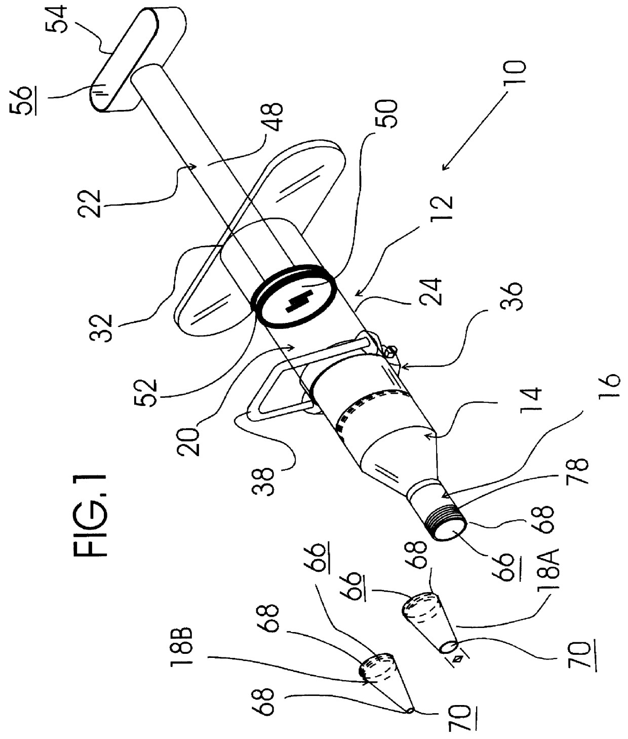
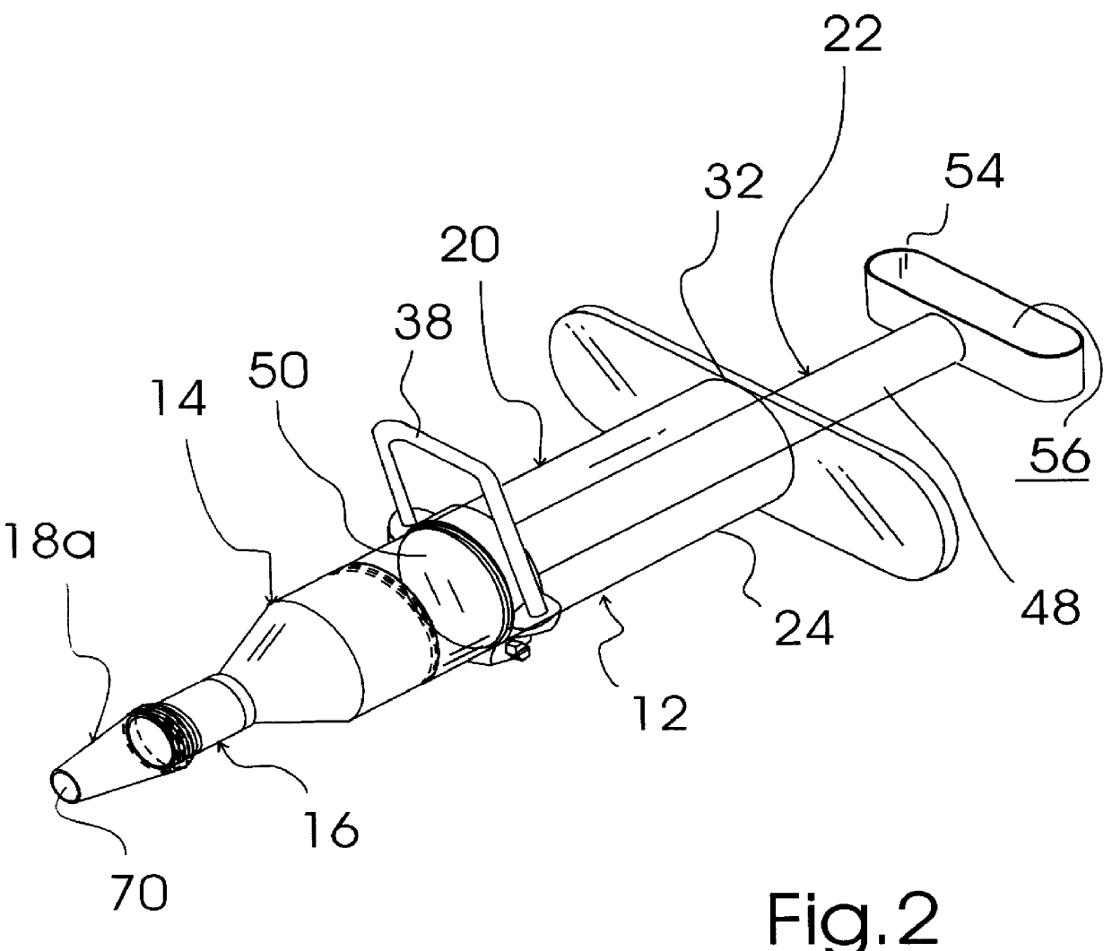
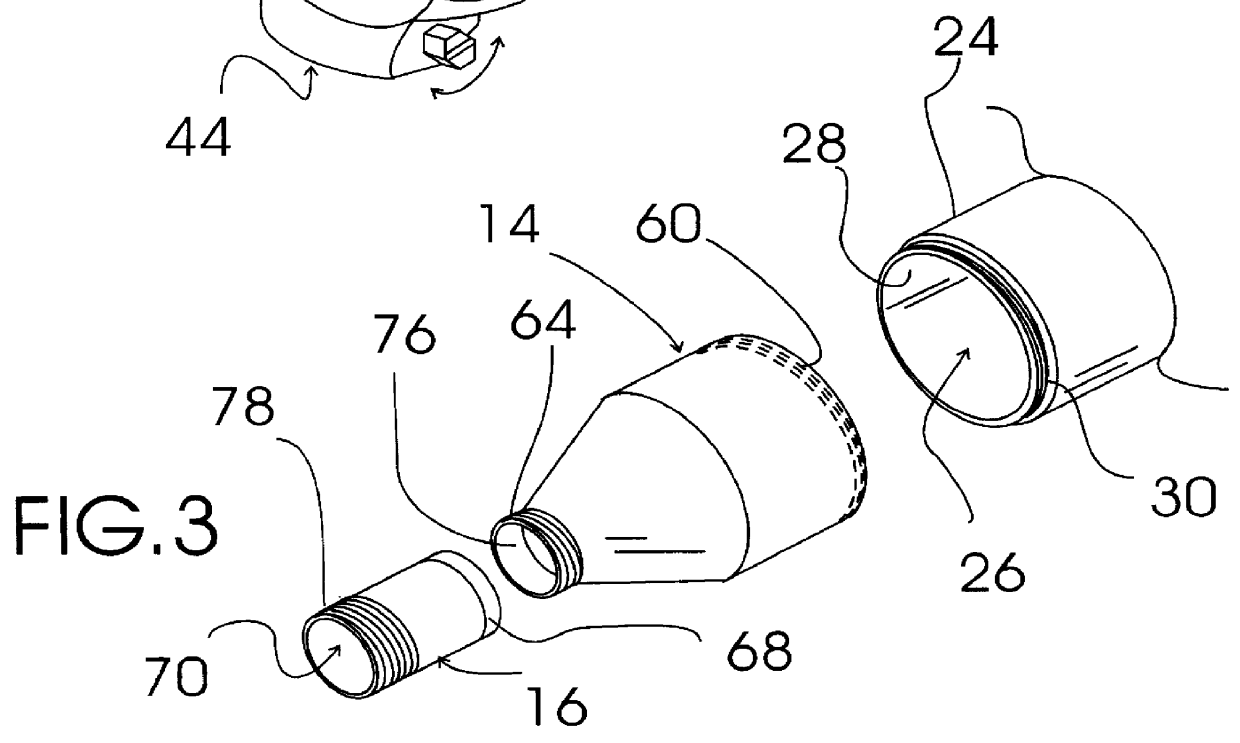
FIGS. 1-4 shows various aspects of an exemplary embodiment of the grout dispenser system of the present invention generally designated 10. Grout dispenser system 10 includes an injector assembly, generally designated 12; a tubular injector nose piece, generally designated 14; and three nozzle tips including one straight nozzle tip, generally designated 16, and two tapered nozzle tips, generally designated 18a, 18b, respectively.

Injector assembly 12 includes a cylinder tube assembly, generally designated 20 and a plunger assembly, generally designated 22. Cylinder tube assembly 20 includes a plastic injector tube having a piston passageway 26 defined by a smooth cylinder bore wall 28 and formed between an open exteriorly threaded tip end 30 and an open handle end 32 and a detachable hand grip assembly, generally designated 36 including a U-shaped gripping portion 38 having the gripping portion ends 40a, 40b thereof permanently attached to a band 42 of a worm drive hose clamp, general...


PUM


Abstract

A grout dispensing system that includes an injector having a number of user selectable dispensing nozzles that allow an individual to select a desired dispensing opening diameter for a particular job and which includes a piston/plunger for forcing grout out of the nozzle under pressure into the gap between tiles to ensure that a proper amount of grout is within the gap. The injector includes a hand grip assembly that is gripped by a user with one hand while simultaneously pushing the plunger/piston into the injector cylinder.

Description

TECHINICAL FIELDThe present invention relates to tile setting equipment and more particularly to a grout dispenser system that includes an injector assembly, a tubular injector nose piece, and a number of nozzle tips including one straight nozzle tip and one tapered nozzle tip; the injector assembly being constructed of plastic and including a cylinder tube assembly and a plunger assembly; the cylinder tube assembly including an injector tube having a piston passageway defined by a smooth cylinder bore wall and formed between an open exteriorly threaded tip end and an open handle end and a detachable hand grip assembly including a U-shaped gripping portion having the gripping portion ends thereof permanently attached to the band of a worm drive hose clamp of sufficient size to slide over the exterior of the injector tube and tightenable to grip and adjustably secure the detachable hand grip assembly to the injector tube; the plunger assembly including a shaft terminating at one end ...

Claims


Application Information

Patent Timeline
IPC IPC(8): B05C17/005B05C17/01G01F11/02
CPCG01F11/025B05C17/01
Inventor FUNK, SHANNON J.
Owner FUNK SHANNON J
Why Eureka
Try Eureka