
Kitchen ventilation hood apparatus

a technology for ventilation hoods and kitchens, which is applied in ventilation systems, heating types, and domestic stoves or ranges. it can solve the problems of harmful and potentially hazardous, irritating by-products of cooking, and affecting the health of consumers, so as to reduce the escape, reduce the escape, and the size and design are sufficien

Active Publication Date: 2010-02-02
UNIFIED BRANDS
View PDF59 Cites 13 Cited by
  • Summary
  • Abstract
  • Description
  • Claims
  • Application Information

AI Technical Summary

Benefits of technology

The arched interior surface design allows for effective removal of cooking by-products with lower airflow, reducing energy waste and utility bills by optimizing airflow direction and minimizing the need for make-up air.

Problems solved by technology

Cooking creates undesirable by-products, such as heat, steam, grease, odors, and by-products of gas combustion used to heat the appliances.
These cooking by-products pollute the air in a home or commercial environment if they are not safely removed.
These cooking by-products are irritating, harmful and potentially hazardous.
The hood is like a small room wherein too much airflow is as harmful as too little.
If too much air is removed from a well insulated building, a negative pressure results rendering the ventilation system ineffective unless expensive make-up air is introduced.
This can be a waste of heated or air conditioned air which must be replaced by heating and air conditioning systems.
Most current systems have angular interior surfaces which do not adequately direct air flow, resulting in a large necessary amount of airflow through kitchen ventilation hoods to adequately remove offending substances and a waste of conditioned kitchen air.
This resulting inefficiency increases the owner's utility bills and needlessly wastes energy.
These deficiencies constitute a technical problem to be solved.

Method used


Image

  • Kitchen ventilation hood apparatus
  • Kitchen ventilation hood apparatus
  • Kitchen ventilation hood apparatus

Examples


Embodiment Construction

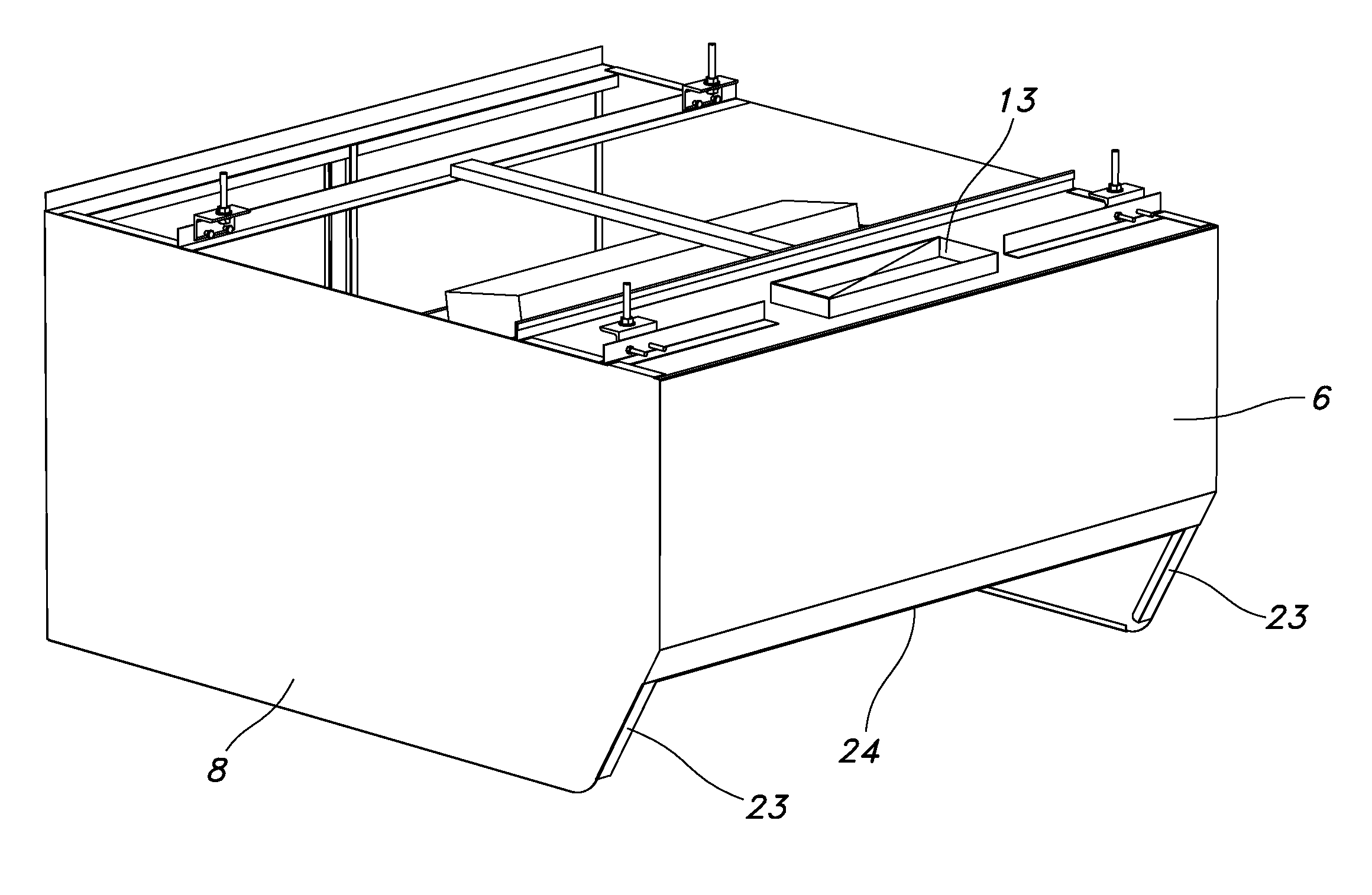
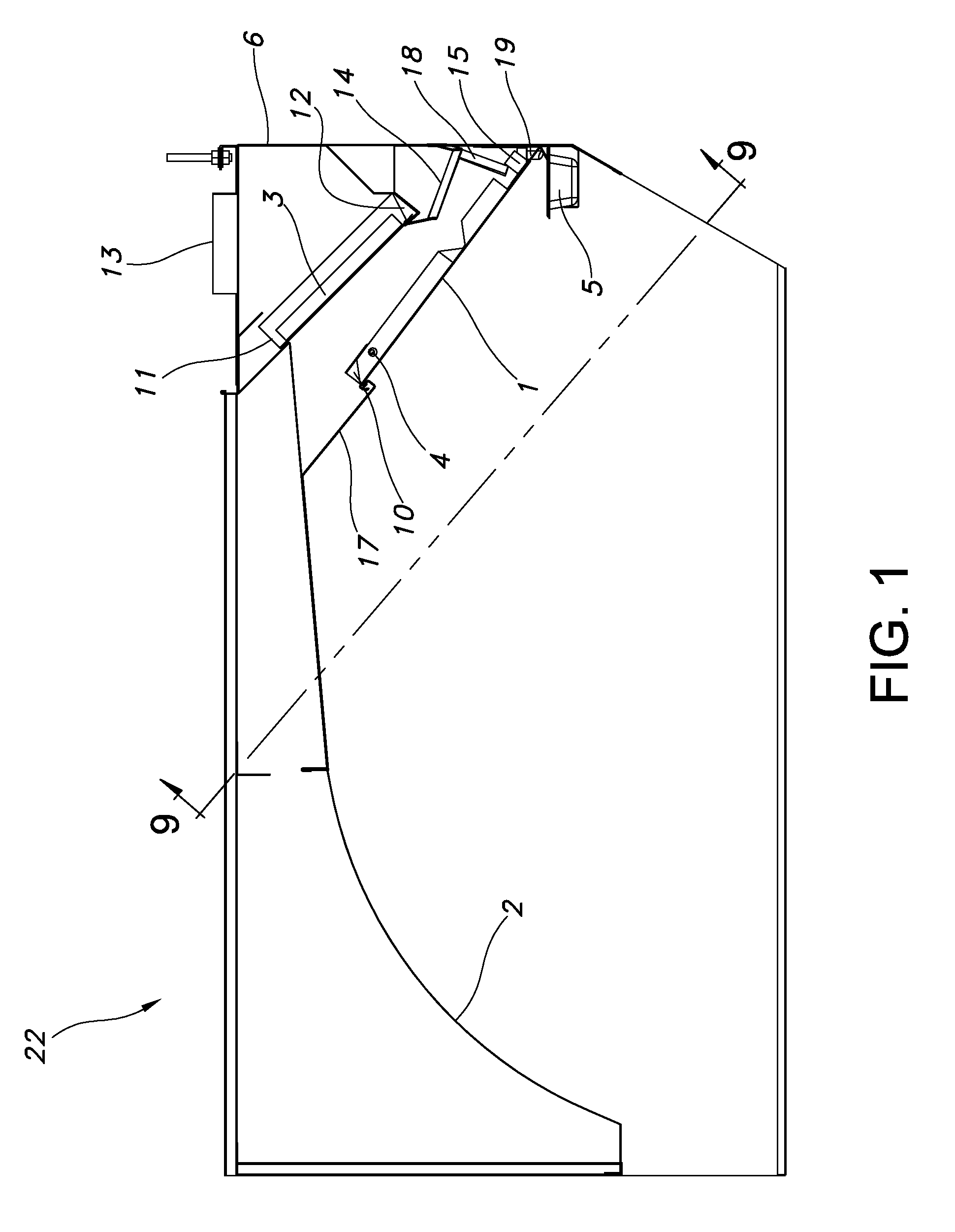
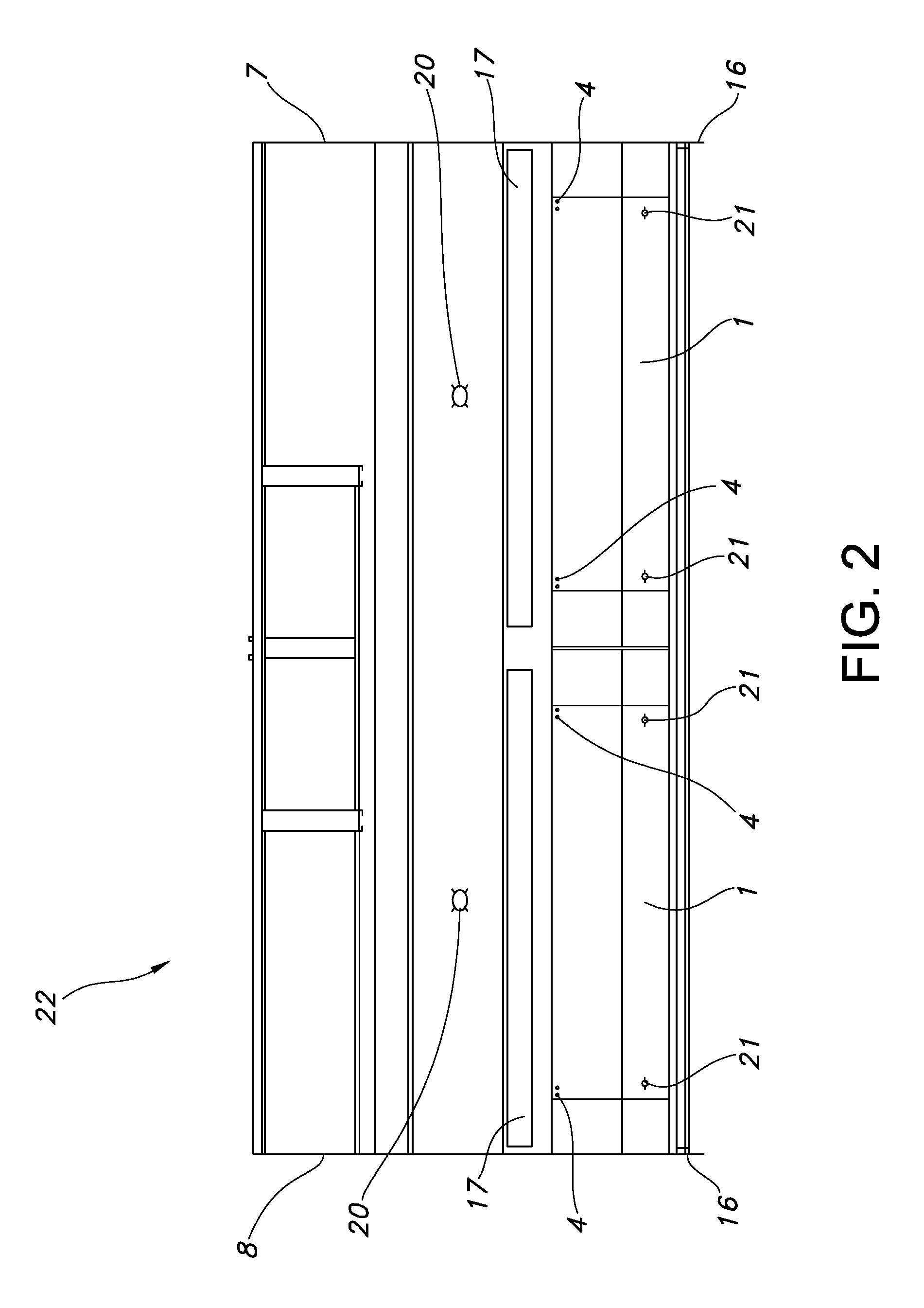
[0013]In referring to the drawings, in particular the FIGS. 1, 2, 3, and 4 there is shown a kitchen ventilation hood 22 of this invention, which is designed to efficiently remove products of gas combustion and grease and / or steam vapors emanating from a cooking surface while minimizing air flow to keep clean conditioned air from being drawn from the kitchen. The kitchen ventilation hood 22 has a housing made of front shield 6, right side shield 7, and left side shield 8. The back interior surface of the kitchen ventilation hood 22 in the preferred embodiment is an arched interior hood surface 2. This arched interior surface design allows for a decreased air flow, while still removing the steam vapors and products of gas combustion from the area of the cooking surface (not shown). A front baffle 1 is provided and above the front baffle is the air intake gap 17, through which the air to be ventilated passes when exiting the kitchen ventilation hood 22. Air to be ventilated enters thro...


PUM


Abstract

The present invention provides a kitchen ventilation hood for ventilating the area above a cooking area and for exhausting air containing cooking by-products from a cooking station to an external environment through an exhaust duct while using a reduced airflow. The kitchen ventilation hood of the present invention is designed to minimize the required airflow through the hood in order to thoroughly evacuate the cooking by-products. The kitchen ventilation hood of the current invention has a structure incorporating an arched interior hood surface that directs the air to be ventilated through the air intake gap and the grease filter. The more efficient airflow resulting from the arched interior hood surface allows for removal of cooking by-products with a lower airflow than that required by currently available ventilation hoods. As such, the kitchen ventilation hood of the present invention represents a significant improvement over prior ventilation hoods.

Description

CROSS REFERENCE RELATED TO PATENT APPLICATION[0001]This application claims the benefit of U.S. Ser. No. 60 / 821,152 filed Aug. 2, 2006 under 35 U.S.C. § 1.119(e) (hereby specifically incorporated by reference in its entirety)FIELD OF THE INVENTION[0002]The present invention relates generally to ventilation hoods and more specifically to an apparatus and system for safely and efficiently ventilating the area above a stovetop or similar cooking device.BACKGROUND OF THE INVENTION[0003]Cooking creates undesirable by-products, such as heat, steam, grease, odors, and by-products of gas combustion used to heat the appliances. These cooking by-products pollute the air in a home or commercial environment if they are not safely removed. These cooking by-products are irritating, harmful and potentially hazardous. Accordingly, a multitude of ventilation systems have been developed to draw the cooking by-products away from the immediate vicinity of the cooking area and to expel this contaminated ...

Claims


Application Information

Patent Timeline
Patent Type & Authority Patents(United States)
IPC IPC(8): F24C15/20
CPCF24C15/20
Inventor NEGANDHI, DIPAK J.DVORAK, JOSEPH W.ERVIN, JAMES WILLIAMDELORENZO, MARK
Owner UNIFIED BRANDS
Learn More