Enhanced duty cycle design for micro thermoelectromechanical coolers

a technology of thermoelectric cooler and duty cycle, which is applied in the direction of refrigerating machines, machines using electric/magnetic effects, lighting and heating apparatus, etc. it can solve the problems of insufficient thermoelectric effect utilization, few applications can effectively utilize thermoelectric effects, and undesirable properties of thermoelectric elements such as high cost and low efficiency, and achieve the effect of outweighing the desirable properties of thermoelectric devices

Inactive Publication Date: 2000-12-19
IBM CORP
View PDF10 Cites 81 Cited by
  • Summary
  • Abstract
  • Description
  • Claims
  • Application Information

AI Technical Summary

Problems solved by technology

The utilization of thermoelectric devices in industry has, to date, been restricted to very specialized applications.
Due to inefficiencies, very few applications can effectively utilize thermoelectric effects.
The undesirable properties of thermoelectric elements such as high cost and low efficiency are outweighed by the desirable properties of thermoelectric devices.
Miniature vapor compression cooling is not available for small cooling applications.
However, accomplishing such cooling in the confines of an ever decreasing size poses new challenges.
Hot spots within an integrated circuit can cause a host of related failures.
As the dimension of integrated circuits decrease and become more compact, the dissipation of internally generated heat becomes an increasing problem.
The inefficiency of thermoelectric devices is a key negative aspect of implementing a thermoelectric cooling design.
Therefore, Peltier device thermoelectric cooling has not been considered a broadly applicable technology for cooling electronic and optical devices.
Equation 1 clearly reflects how quickly the Peltier device becomes inefficient.
(T.sub.cold / .DELTA.T) as .gamma..cuberoot..infin.. To date it has been very difficult to develop a thermoelectric material which yields high values of ZT.
However, even with these materials, thermoelectric devices have not produced practical cooling solutions.
Another constraint of Peltier device cooling is that only a limited temperature excursion below ambient temperature is attainable.
The temperature differential limitation arises from the fact that the effective temperature differential is constrained by efficiency.
Thus, there are a number of very fundamental constraints on efficiency and differential temperature that limit the practical utilization of conventional thermoelectric elements for cooling applications.
Typically, each Peltier device is small in dimension and can only transport a finite amount of heat.

Method used


Image

  • Enhanced duty cycle design for micro thermoelectromechanical coolers
  • Enhanced duty cycle design for micro thermoelectromechanical coolers
  • Enhanced duty cycle design for micro thermoelectromechanical coolers

Examples


Embodiment Construction

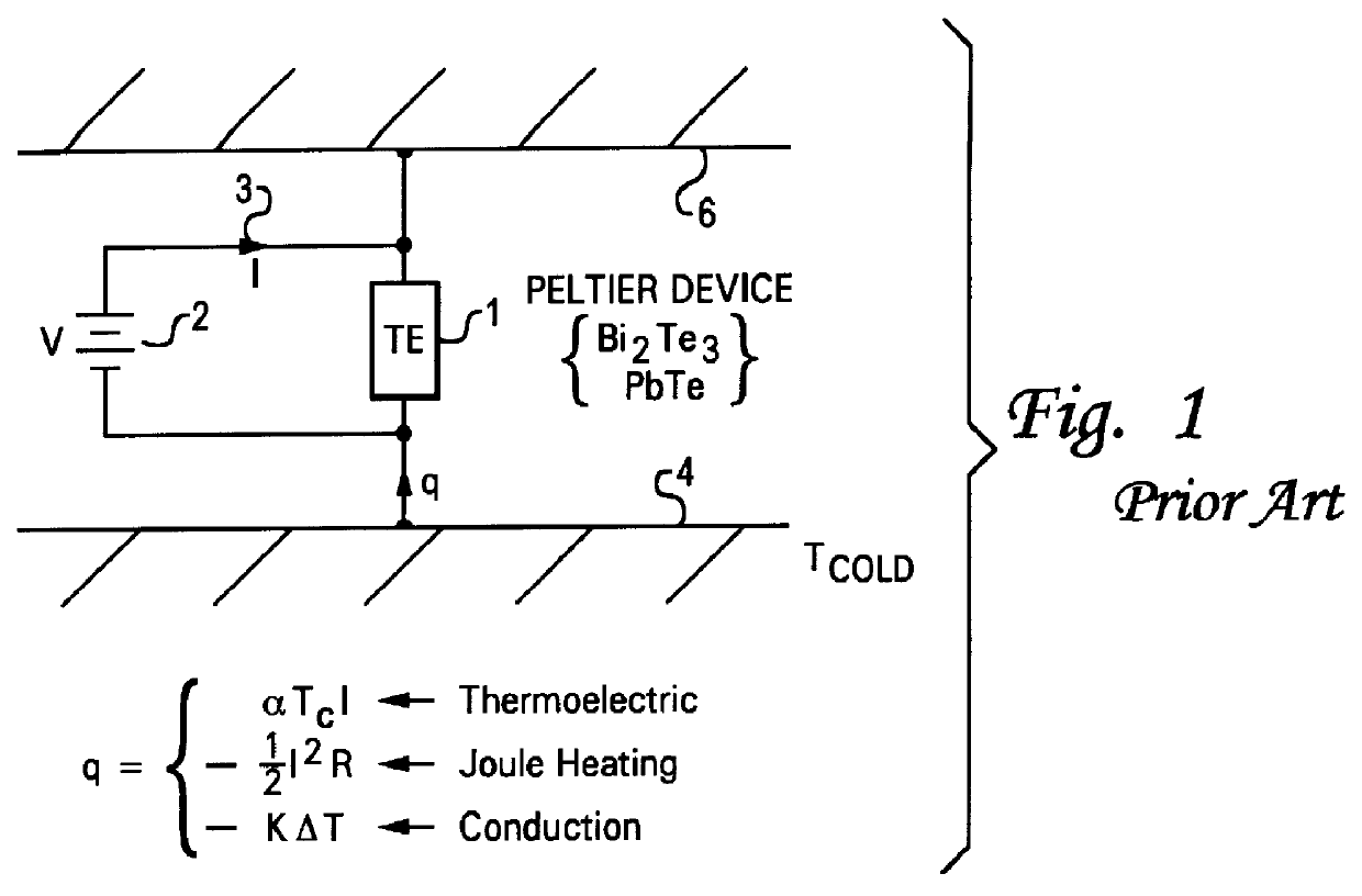
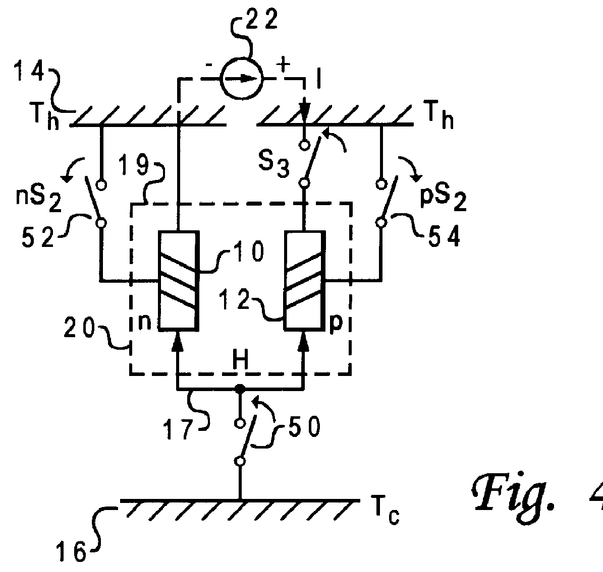
With reference now to the figures and in particular with reference to FIG. 2, there is depicted a novel interconnection of Peltier device to a hot source 14 and a cold sink 16 in accordance with one embodiment of the present invention. During operation, Peltier device 15 heats hot source 14 and cools cold sink 16. FIG. 2 illustrates a simplified schematic depicting a peltier device which is coupled to cold sink 16 via first thermoelectric switch 18.

First thermoelectric switch 18 thermally couples cold sink 16 to Peltier device 15. Second thermal switch 38 couples hot source 14 to Peltier device 15. Thus, Peltier device 15 is electrically and thermally coupled to cold sink 16 when first thermoelectric switch 18 is in the closed position. In the illustrated embodiment, Peltier device 15 is continuously thermally and electrically coupled to hot source 14 at first end 19 of Peltier device 15 through a thermal path having little thermal resistance.

Second end 17 of Peltier device 15 is th...


PUM


Abstract

A thermoelectric cooling apparatus which includes a Peltier device or a thermoelectric element coupled to a hot source and a cold sink. The hot source dissipates heat produced by the thermoelectric element. The cold sink is coupled to a mass to be cooled. A means for supplying power to the thermoelectric element is provided and a means for selectively thermally coupling the thermoelectric element to the hot source is provided. Selectively thermally switching the thermoelectric element to the hot source allows heat to be dissipated to the hot source when the thermoelectric element possesses excess heat. Dissipating the excess heat when the excess heat is present allows higher efficiencies to be attained in thermoelectric cooling.

Description

1. Technical FieldThe present invention relates in general to enhancing the duty cycle of a thermoelectric cooler element, and in particular to a method and system for achieving greater efficiency from a thermoelectric cooler. Still more particularly, the present invention relates to a method and system of thermally switching a thermoelectric element such that reduced thermal resistance can be attained from a thermoelectric element to a hot source during intermittent periods within a heat transfer cycle of a thermoelectric cooling process.2. Description of the Related ArtThe utilization of thermoelectric devices in industry has, to date, been restricted to very specialized applications. Due to inefficiencies, very few applications can effectively utilize thermoelectric effects. The undesirable properties of thermoelectric elements such as high cost and low efficiency are outweighed by the desirable properties of thermoelectric devices. Recently, there have been significant advances ...

Claims


Application Information

Patent Timeline
Patent Type & Authority Patents(United States)
IPC IPC(8): F25B21/02H01L35/00F25B21/00
CPCF25B21/02H01L35/00F25B2321/0212H10N10/00F25B21/00
Inventor GHOSHAL, UTTAM SHYAMALINDU
Owner IBM CORP
Why Eureka
Try Eureka