Garment-concealable jewelry case having parallel-running compartments and integrated jewelry trays for storing and organizing jewelry
What is AI technical title?
AI technical title is built by PatSnap AI team. It summarizes the technical point description of the patent document.
a jewelry case and parallel-running technology, applied in the field of improvement, can solve the problems of affecting the appearance of the jewelry case, the inability to maintain the necklace in a tangle-free configuration, and the design of the prior art necklace holder and organizer design, etc., and achieve the effect of convenient cleaning
Inactive Publication Date: 2000-12-19
GEMINI MARKETING
View PDF37 Cites 41 Cited by
Summary
Abstract
Description
Claims
Application Information
AI Technical Summary
This helps you quickly interpret patents by identifying the three key elements:
Problems solved by technology
Method used
Benefits of technology
Benefits of technology
Another object of the present is to provide such a garment-concealable jewelry case, wherein each jewelry post contacts the rear surface of the front cover panel in order to prevent supported articles of jewelry from sliding or otherwise falling off the support post when the front cover panel is closed and the jewelry case is being transported or otherwise subjected to external forces, as experienced when moving clothes around in a closet environment.
Another object of the present invention is to provide such a garment-concealable jewelry case, wherein the front cover panel can b e easily opened to reveal organized articles of jewelry when the case is lying flat in a suitcase.
Another object of the present invention is to provide such a garment concealable jewelry case, which is designed to swivel about its support hook within a closet so as to face the user and enable easy access to the articles of jewelry supported therewithin. Another object of the present invention is to provide such garment-concealable jewelry case, which is made from a durable colored plastic that is easy to clean.
Problems solved by technology
However, such prior art jewelry cases have suffered from a number of shortcomings and drawbacks so as to not be commercially practical.
In particular, prior art necklace holder and organizer designs, configured in the shape of clothes hangers, are generally heavy, flimsy, space consuming, unattractive, expensive to manufacture, and fail to maintain necklaces in a tangle-free configuration if the organizer is tipped or tilted during movement or transportation operations.
In addition, such prior art necklace holder and organizer designs often tend to catch on clothes used to conceal the same.
Method used
Image
Click on the blue label to locate the original text in one second.
Reading with bidirectional positioning of images and text.
Examples
Embodiment Construction
Referring now to the accompanying Drawings, the Detailed Description of the Illustrative Embodiment will now be described in detail hereinbelow, wherein like elements shall be denoted by like reference numerals.
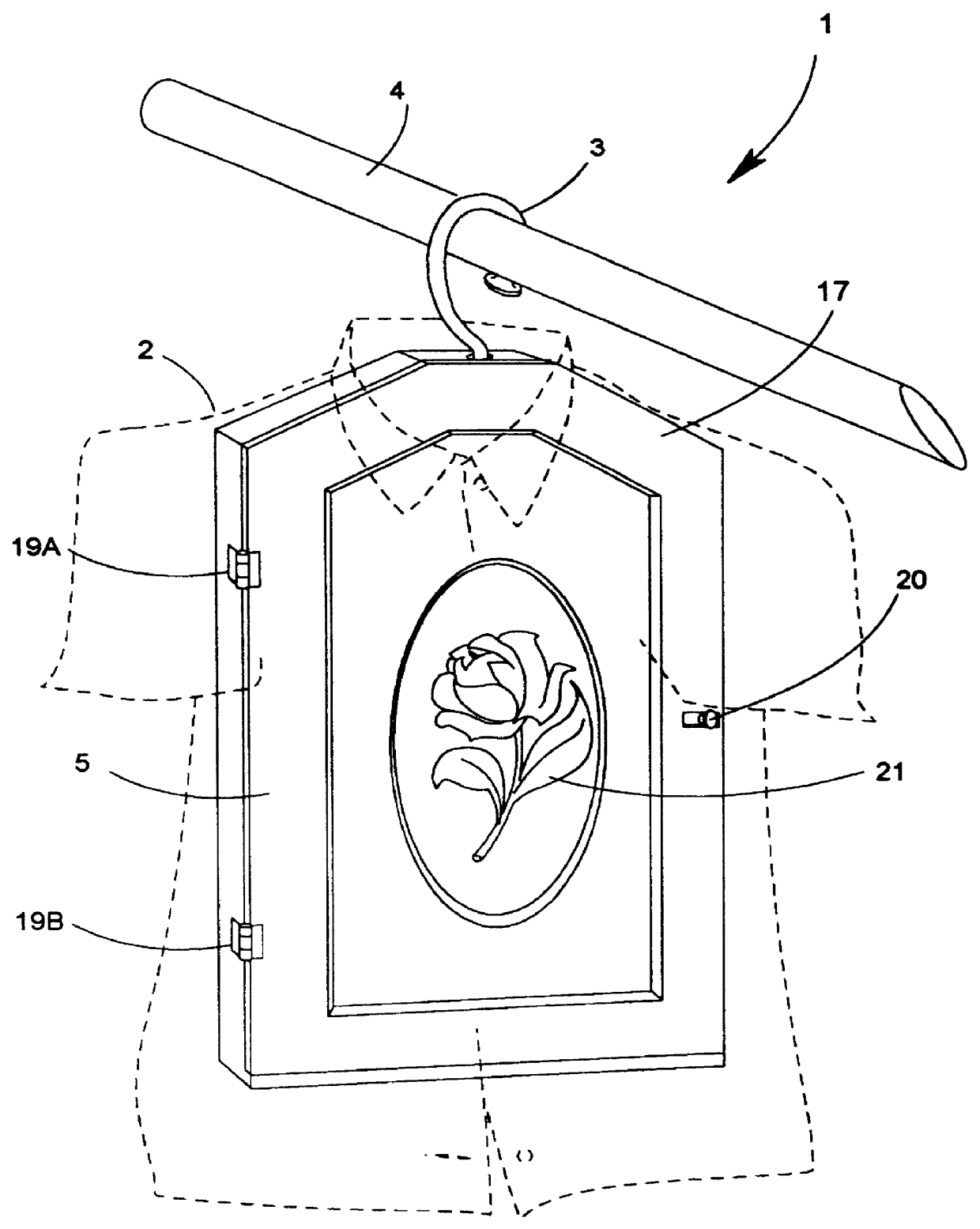
As shown in FIG. 1, the jewelry case of the illustrative embodiment of the present invention indicated by reference numeral 1 has a very thin housing that is dimensioned so that a shirt, blouse or coat 2 (depicted in dotted lines) can be fitted thereover to cover the storage case when it is hung from its retractable / projectable support hook 3 on a closet rod 4 supported inside a clothes closet. In the illustrative embodiments, the case housing 5 has maximum length dimension of about 18.5 inches, a maximum width dimension of about 11 inches, and a depth (i.e. thickness) dimension of about 1.0 inch or less, to provide an ultra-thin low-height profile design that is easily concealed under a short, blouse or coat. Preferably, the case housing is made from a lightweight, yet durab...
PUM
Abstract
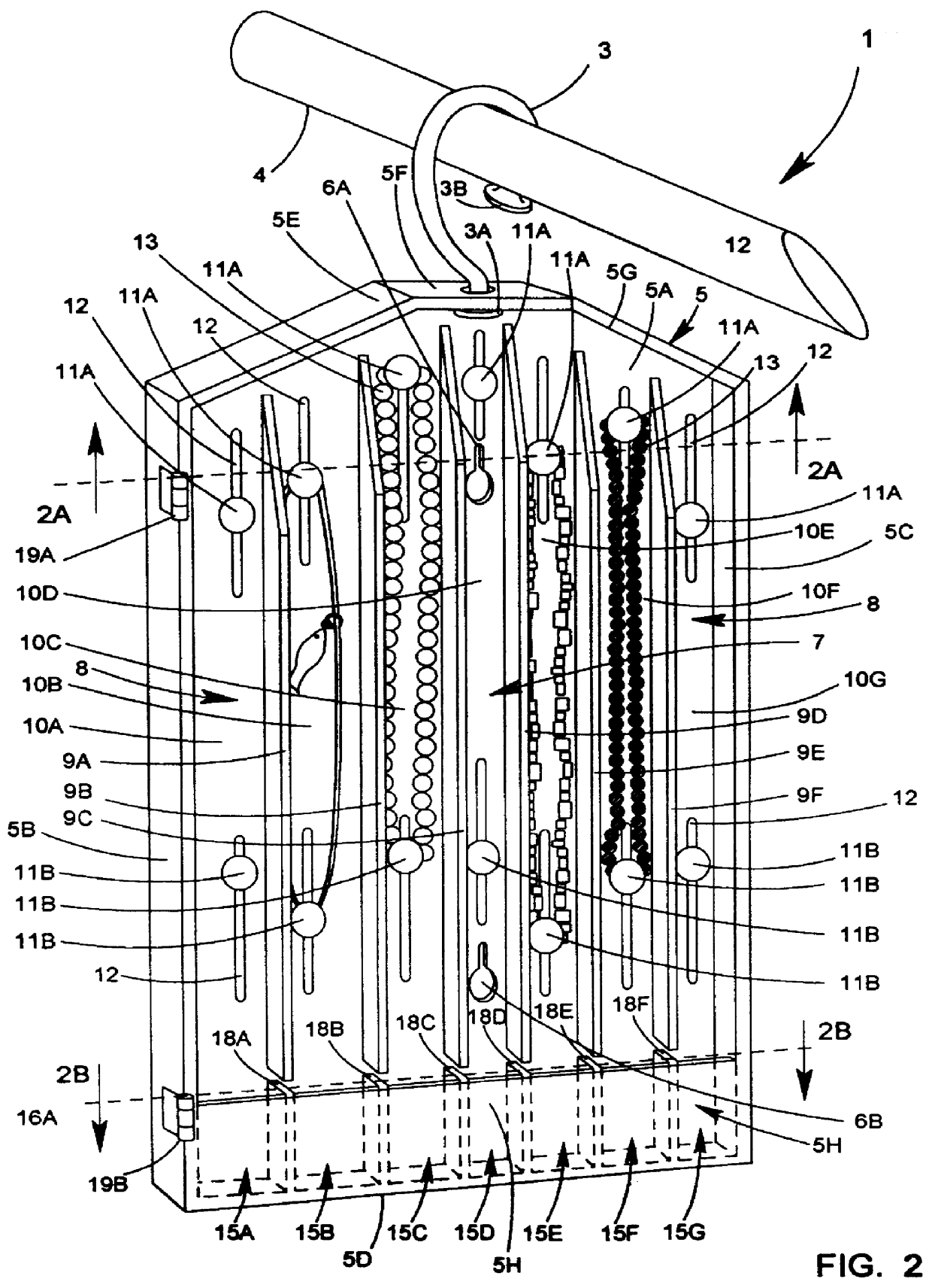
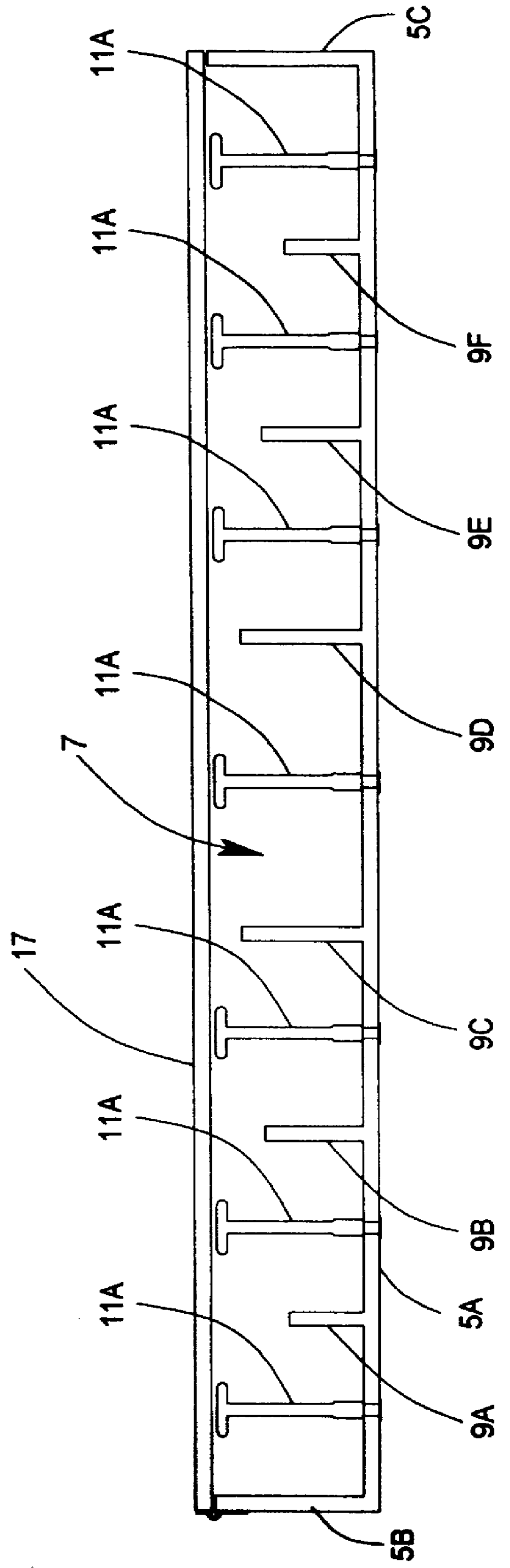
A garment-concealable jewelry case having a front opening with a front cover panel portion that can be either moved or configured to reveal a plurality of parallel-running isolated storage compartments each having an interior storage space which is accessible through a front opening revealed when the front cover panel is removed or reconfigured. Through the front opening of each storage compartment, one or more necklaces, pendants, bracelets or other strands of jewelry can be securely hung on a pair of jewelry support posts adapted for spatial separation on the back wall portion of the storage compartment in order to accommodate the length of jewelry strands being supported. The bottom portion of each parallel-running isolated compartment has a stationary front panel portion which, cooperating with the other wall portions of the storage compartment, provides a five sided stationary storage tray accessible through the opening of the respective storage compartment and within which articles of jewelry such as rings, watches, earrings and / or tie tacks can be placed for organization and storage. The front cover panel has a tray cover panel integrated therewith, which closes off each jewelry storage compartment when the front cover panel is positioned over the access opening formed in the case housing. When the front cover panel is closed, the jewelry support posts contact the rear surface of the front cover panel to prevent supported articles of jewelry from falling off and tossing about within the storage compartment during usage, including travel.
Description
1. Field of InventionThe present invention relates to an improved device for storing and organizing articles of jewelry including necklaces and bracelets.2. Brief Description of the Prior ArtFor ages, jewelry such as necklaces, bracelets, rings and pendants, have been worn by men and women alike for ornamental and symbolic reasons alike.When not being not worn, such jewelry is typically placed into a storage case for safe keeping. Over the years, numerous different types of jewelry storage cases have been developed. Examples of such prior art jewelry cases are disclosed in U.S. Pat. Nos. 4,401,219; 4,620,651; 4,720,987; 4,848,585; 4,854,656; 5,246,103; 5,246,103; 5,295,587; 5,427,230; Des. 167,836; and Des. 247,084, each being incorporated herein by reference.U.S. Pat. Nos. 4,848,585, 4,854,656, 5,246103 teach how to make jewelry cases for storing necklaces in a way that prevents tangling.U.S. Pat. Nos. 4,620,651 and 4,401,219 teach how prior art jewelry cases are concealed by garme...
Claims
Application Information
Patent Timeline
Application Date:The date an application was filed.
Publication Date:The date a patent or application was officially published.
First Publication Date:The earliest publication date of a patent with the same application number.
Issue Date:Publication date of the patent grant document.
PCT Entry Date:The Entry date of PCT National Phase.
Estimated Expiry Date:The statutory expiry date of a patent right according to the Patent Law, and it is the longest term of protection that the patent right can achieve without the termination of the patent right due to other reasons(Term extension factor has been taken into account ).
Invalid Date:Actual expiry date is based on effective date or publication date of legal transaction data of invalid patent.

