Heated water dispensing system

a technology of water dispensing system and water dispenser, which is applied in the direction of heating apparatus, applications, lighting and heating, etc., can solve the problems of inability of existing dispensers to produce water of a desired temperature quickly, inconvenient and impractical to have to modify the dispenser, and modify the machin

Inactive Publication Date: 2000-12-26
BUNN O MATIC
View PDF13 Cites 121 Cited by
  • Summary
  • Abstract
  • Description
  • Claims
  • Application Information

AI Technical Summary

Benefits of technology

Accordingly, it is a general object of the present invention to provide a heated w...

Problems solved by technology

In particular, it is inconvenient and impractical to have to modify the dispenser whenever a water dispensing temperature outside the current operating range of the dispenser is needed.
Unfortunately, in a restaurant or other cooking environment the need to modify the machine arises frequently because of the different water temperatures necessary to produce different types of food.
Another drawback is the inability of existing dispensers to produce water of a desired temperature quickly.
The water supply for dispensers typically comprise unheated tap water; the heating up of relatively cool incoming tap water using an electric resistance element to the relatively high temperatures necessary for cooking can be a fairly slow process.
Such delay can be particularly disadvantageous in a restaurant or other cooking environment in which efficient service is important to the viability of the restaurant.
A further drawback is wastage of hot water, because of user-related error in...

Method used


Image

  • Heated water dispensing system
  • Heated water dispensing system
  • Heated water dispensing system

Examples


Embodiment Construction

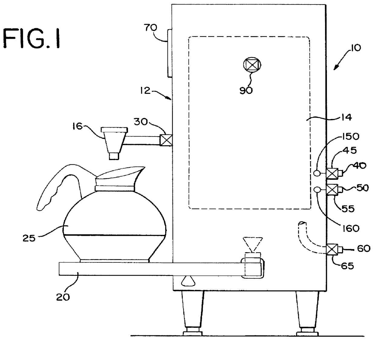
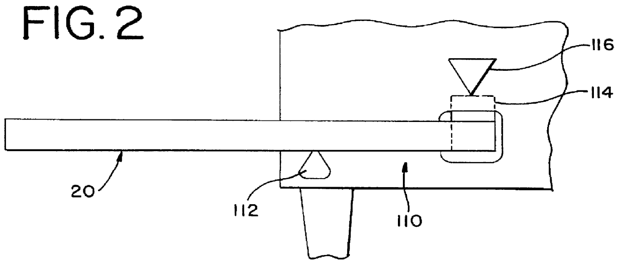
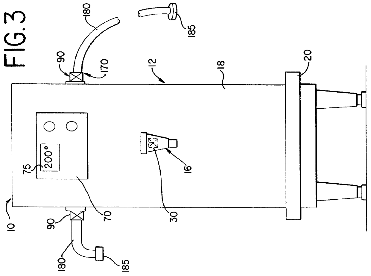
Reference is now invited to FIGS. 1 and 3 which are, respectively diagrammatic side and front elevational views of a heated water dispensing apparatus 10 according to the invention. As illustrated, a heated water dispensing apparatus 10, according to the invention, includes a housing 12. The housing 12 retains, within its interior, a heated water reservoir 14 for holding a quantity of hot water. A faucet or spigot 16 is coupled to the reservoir 14 for dispensing water from the reservoir 14 into a receptacle or container 25. In the illustrated embodiment, the faucet or spigot 16 is provided on a front panel 18 of the housing 12. Conveniently, a container platform 20 is provided beneath the faucet or spigot 16 on which to rest a receptacle 25 during dispensing. A dispensing valve 30 is coupled to the faucet 16 and the reservoir 14 for controlling the flow of water from the reservoir 14 through the faucet 16.

The heated water dispensing apparatus 10 also includes a first water inlet 40,...


PUM


Abstract

A heated water dispensing apparatus has been described. The heated water dispensing apparatus includes a reservoir for retaining a quantity of water, a selector for selecting a temperature of water and a volume of water to be dispensed, and a controllable dispense valve for automatically dispensing water from the reservoir. The heated water dispensing apparatus also includes a weighing assembly which generates a weight control signal relating to the volume of water dispensed through the dispense valve and at least one device outlet valve for providing heated water to a remote device. The heated water dispensing apparatus also includes a controller. The controller operates the dispense valve in accordance with the weight control signal so that a selected volume of water is automatically and accurately dispensed. The controller also operates the dispense valve to prevent dispensing of water through the dispense valve before water of a selected temperature has been produced. The controller operates the device outlet valve so that a predetermined quantity of water at a predetermined flowrate and a predetermined temperature is dispensed to a selected remote device.

Description

BACKGROUND TO THE INVENTIONThe present invention relates to a heated water dispensing apparatus and in particular to an improved heated water dispensing apparatus capable of automatically dispensing preselected volumes of water at preselected temperatures.It is desirable in restaurants and other institutional cooking establishments to have a source of hot water for various cooking purposes. For example, hot water is necessary in the preparation of soups, pastas, gravies, pizza dough and other dishes. Additionally, a source of hot water is desirable in the preparation of hot chocolate, tea, coffee, and other hot or brewed beverages. Moreover, a source of hot water is desirable for various cleaning purposes.To supply hot water for these and other purposes, hot water dispensers have come into increasing use. Typically, these units employ a hot water reservoir in which water is heated by an electric resistance heater element. The application of electric current to the heating element is...

Claims


Application Information

Patent Timeline
IPC IPC(8): A47J31/56A47J31/44
CPCA47J31/56G01G17/06G01G19/52
Inventor ANSON, JAMES H.
Owner BUNN O MATIC
Why Eureka
Try Eureka