Aerofoil profile with variable profile adaptation

a technology of variable profile and aerofoil, which is applied in the direction of mechanical equipment, machines/engines, transportation and packaging, etc., can solve the problems of scarce improvement in performance of the fast flight phase of subsonic long-distance aircraft, constant exposure to new flight conditions,

Inactive Publication Date: 2000-12-26
DEUTSCHES ZENTRUM FUER LUFT & RAUMFAHRT EV
View PDF29 Cites 29 Cited by
  • Summary
  • Abstract
  • Description
  • Claims
  • Application Information

AI Technical Summary

Problems solved by technology

They are exposed to constantly changing external conditions from take-off to landing of the aircraft, and are additionally also constantly exposed to new flight conditions as a result of operation, e.g. of fuel consumption and the resulting weight loss.
Scarcely any improvements in performance have been achieved for the fast flight phase of subsonic long-distance aircraft at high and medium altitudes.

Method used


Image

  • Aerofoil profile with variable profile adaptation
  • Aerofoil profile with variable profile adaptation
  • Aerofoil profile with variable profile adaptation

Examples


Embodiment Construction

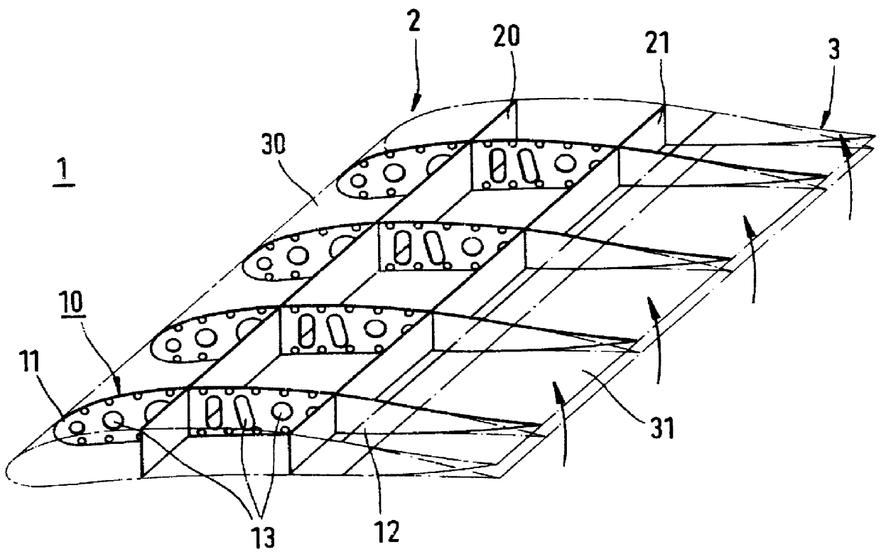
FIG. 1 shows a perspective view of a wing 1 (which may be part of a plane's tail) with a front profile 2 and a rear profile 3. The rear profile 3 is in the form of an aerofoil profile of the flexible region of a Fowler flap.

The wing 1 has ribs 10 in the form of longitudinal ribs and transverse supports 20, 21 connecting these. The overall arrangement is enclosed by a skin panel 30, 31. The longitudinal ribs 10 are divided into a rigid region 11 and a flexible region 12. The rigid region 11 is formed between the front extension of the longitudinal rib essentially to the transverse support 21. The flexible region 12 extends from the transverse support 21 up to the rear tip of the longitudinal rib, i.e. to the trailing edge of the wing. The rigid region 11 is preferably provided with openings 13. As a result, the stability of the longitudinal rib is maintained, while at the same time being produced in a manner suitable for lightweight construction. The rib is preferably produced from a...


PUM


Abstract

In an aerofoil profile with variable profile adaptation and rigid rib structure, the aerofoil profile has a flexible rib structure with rib elements, which are arranged in segments and are articulated to one another in the form of a kinematic chain in order to transmit movement, a skin panel capable of sliding on this and also at least one driving means for moving the flexible rib structure.

Description

DESCRIPTION1. Technical FieldThe invention relates to an aerofoil profile with variable profile adaptation and rigid rib structure as well as to a method of operating such an aerofoil profile.2. Background of Related ArtSupport surfaces in the form of aerofoil profiles are known in the application to aircraft. They are exposed to constantly changing external conditions from take-off to landing of the aircraft, and are additionally also constantly exposed to new flight conditions as a result of operation, e.g. of fuel consumption and the resulting weight loss. Nevertheless, the design of known aerofoil profiles in the form of wings of modem subsonic commercial aircraft continues to be optimized only for one operating point. In order to achieved optimum operating conditions in the different phases of a flight, flaps have been used in commercial aircraft for many years, by means of which adaptation of the wing profile can be made mainly in the take-off and landing phase. To assure util...

Claims


Application Information

Patent Timeline
Patent Type & Authority Patents(United States)
IPC IPC(8): B64C3/00B64C3/48F03D7/02
CPCB64C3/48F03D7/0232Y02E10/723Y02E10/72
Inventor PIENING, MATTHIASMONNER, HANS PETER
Owner DEUTSCHES ZENTRUM FUER LUFT & RAUMFAHRT EV
Why Eureka
Try Eureka