Clip testing unit for a three-dimensional graphics accelerator

a testing unit and accelerator technology, applied in 3d-image rendering, instruments, computing, etc., can solve the problems of limiting performance, bottlenecking the speed at which pixels from processed primitives can be filled into the frame buffer, and requiring a tremendous amount of processing capabilities for applications which display three-dimensional graphics

Inactive Publication Date: 2001-01-02
ORACLE INT CORP
View PDF7 Cites 55 Cited by
  • Summary
  • Abstract
  • Description
  • Claims
  • Application Information

AI Technical Summary

Problems solved by technology

Applications which display three-dimensional graphics require a tremendous amount of processing capabilities.
In general, 3-D graphics accelerators have had three major bottlenecks which limit performance.
A first bottleneck is the transfer of geometric primitive data from main memory to the graphics accelerator over the system bus.
A second bottleneck is the vertex processing requirements (such as transformation, lighting, and set-up) which are performed on the geometric primitives by the graphics accelerator prior to rendering.
A third bottleneck is the speed at which pixels from processed primitives can be filled into the frame buffer.
Clipping is a time-consuming operation.
If the guard band clipping boundary is defined to be too much larger than the regular clipping boundary, however, the deferred rejection of pixels in the guard band region may become more time-consuming than the normal clipping procedure.
Additionally, problematic numeric overflows may occur in vertex processing operations subsequent to the clip test for primitive vertices in a large guard band region.
The guard band comparison requires more processing time, and hence limits system performance.
Additionally, guard band clipping may not be performed consistently in prior art designs, resulting in a shared edge (such as edge 26 in FIG. 1) being clipped differently for different triangles.

Method used


Image

  • Clip testing unit for a three-dimensional graphics accelerator
  • Clip testing unit for a three-dimensional graphics accelerator
  • Clip testing unit for a three-dimensional graphics accelerator

Examples


Embodiment Construction

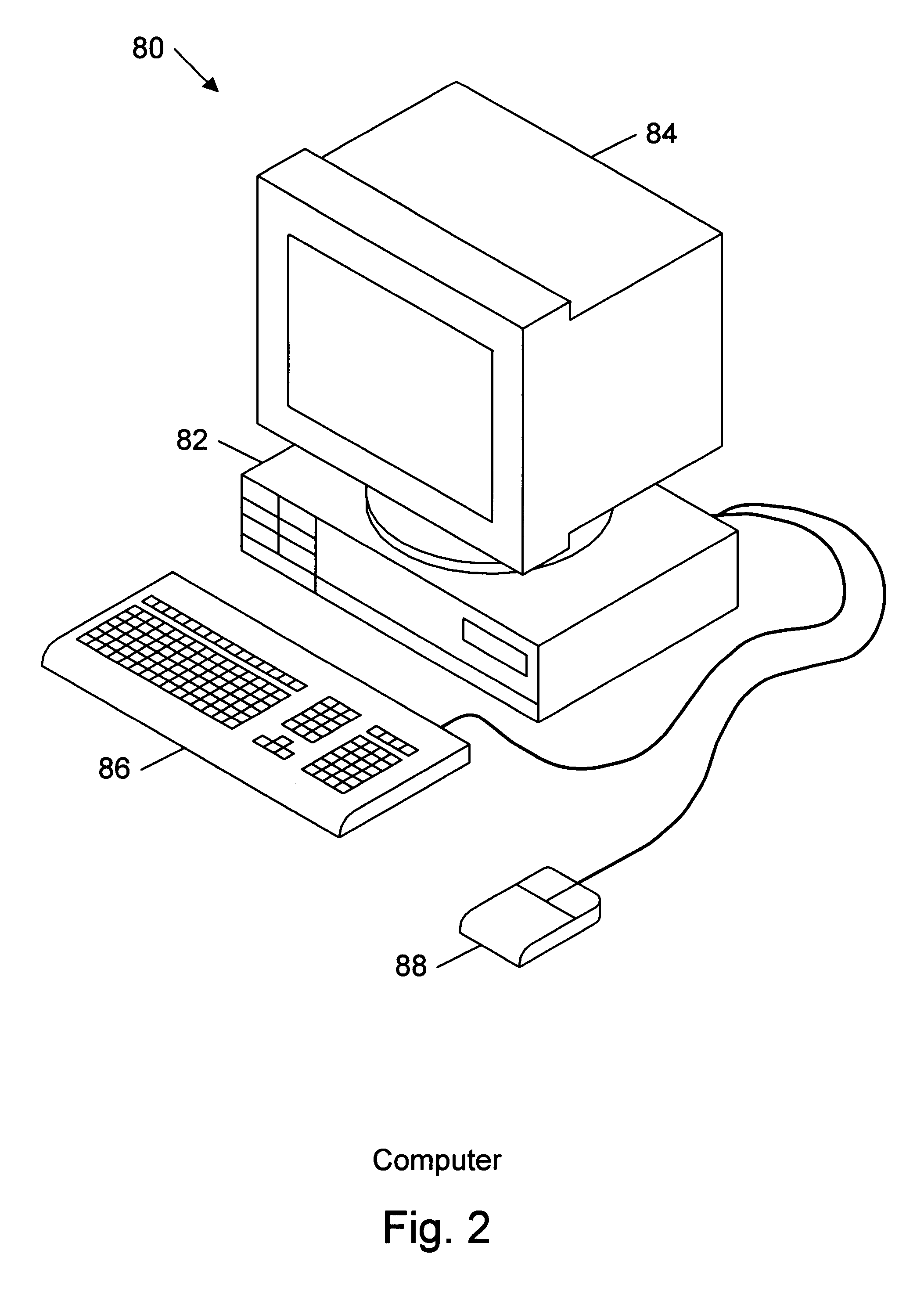
FIG. 2--Computer System

Referring now to FIG. 2, a computer system 80 which includes a three-dimensional (3-D) graphics accelerator according to the present invention is shown. As shown, the computer system 80 comprises a system unit 82 and a video monitor or display device 84 coupled to the system unit 82. The display device 84 may be any of various types of display monitors or devices. Various input devices may be connected to the computer system, including a keyboard 86 and / or a mouse 88, or other input. Application software may be executed by the computer system 80 to display 3-D graphical objects on the video monitor 84.

FIG. 3--Computer System Block Diagram

Referring now to FIG. 3, a simplified block diagram illustrating the computer system of FIG. 2 is shown. Elements of the computer system which are not necessary for an understanding of the present invention are not shown for convenience. As shown, the computer system 80 includes a central processing unit (CPU) 102 coupled to a...


PUM


Abstract

A clip testing unit within a graphics accelerator for comparing a value of a given homogeneous coordinate of a vertex position of a polygon relative to a plurality of clipping planes. The plurality of clipping planes includes both regular and guard band clipping planes. The clip testing unit includes registers for receiving and storing a W value corresponding to the vertex position, as well as a coordinate input register for receiving and storing the given homogeneous coordinate. The W value is conveyed to a guard band W generation unit, which generates a guard band W value in response thereto. The clip testing unit also includes a clip compare unit coupled to receive the W value, the guard band W value and the value of the given coordinate. The clip compare unit receives and compares the W value and the value of the given coordinate, generating one or more first clip signals in response thereto. The one or more first clip signals indicate whether the value of the given coordinate is outside of a regular clipping space defined by the regular clipping planes. Furthermore, the clip compare unit receives and compares the guard band W value and the value of the given coordinate, generating one or more second clip signals in response thereto. The one or more second clip signals indicate whether the value of the given coordinate is outside of a guard band clipping space defined by the guard band clipping planes. Because the first and second clip comparisons are performed substantially concurrently by the clip compare unit, the clip testing performance of the graphics accelerator is advantageously increased.

Description

The present invention relates to a 3-D graphics accelerator, and more particularly to a floating point processor for a 3-D graphics accelerator with improved clip testing capabilities.DESCRIPTION OF THE RELATED ARTA three dimensional (3-D) graphics accelerator is a specialized graphics rendering subsystem for a computer system which is designed to off-load the 3-D rendering functions from the host processor, thus providing improved system performance. In a system with a 3-D graphics accelerator, an application program executing on the host processor of the computer system generates three-dimensional geometry data that defines three-dimensional graphics elements for display on a video output device. The application program causes the host processor to transfer the geometry data to the graphics accelerator. The graphics accelerator receives the geometry data and renders the corresponding graphics elements on the display device.Applications which display three-dimensional graphics requ...

Claims


Application Information

Patent Timeline
Patent Type & Authority Patents(United States)
IPC IPC(8): G06T15/30G06T15/10
CPCG06T15/30
Inventor DEERING, MICHAEL
Owner ORACLE INT CORP
Why Eureka
Try Eureka