Power converting system multiplexed with voltage dividing transformers, the voltage transformers, and controller for the system

a power conversion system and voltage dividing transformer technology, applied in the direction of dc-ac conversion without reversal, process and machine control, instruments, etc., can solve the problem of limiting the constant voltage characteristics, limiting the modulation factor of the npc inverter, increasing the number of switching elements and the cost of the power conversion system

Inactive Publication Date: 2001-01-02
KK TOSHIBA
View PDF3 Cites 51 Cited by
  • Summary
  • Abstract
  • Description
  • Claims
  • Application Information

AI Technical Summary

Problems solved by technology

The NPC inverter of FIG. 1, however, employs capacitors C1 and C2 to divide a DC voltage to increase the number of output levels, and therefore, has limits to the constant voltage characteristics thereof.
This limits a modulation factor of the NPC inverter.
To supply such a high DC voltage, many switching elements must be connected in series, thereby increasing the number of the switching elements and the cost of the power converting system.
This PWM control is low in voltage use ratio and involves unnecessary switching operations to be repeated in synchronization with the carrier frequency, thereby increasing a switching loss, decreasing the efficiency of the power converting system, enlarging a stack and cooling system, and heightening the total cost of the system.
This makes the power converting system uneconomic.
This, however, increases the size, weight, and cost of each reactor.
This also increases an installation space of the power converting system, and the strength of the floor on which the system is installed must be reinforced, thereby increasing the total cost of the system.
Namely, these reactor groups are large and heavy and increase the cost of the power converting system.
In addition, they increase the installation space of the system, and the strength of the floor on which the system is installed must be reinforced, thereby further increasing the cost of the system.

Method used


Image

  • Power converting system multiplexed with voltage dividing transformers, the voltage transformers, and controller for the system
  • Power converting system multiplexed with voltage dividing transformers, the voltage transformers, and controller for the system
  • Power converting system multiplexed with voltage dividing transformers, the voltage transformers, and controller for the system

Examples


first embodiment

FIG. 7 shows the structure of the voltage dividing transformer 10U of the The transformers 10V and 10W have each the same structure as the transformer 10U. The transformer 10U has a multi-leg iron core. Legs of the iron core have windings whose numbers of winds are equal to one another in terms of the polarity of a winding direction represented with a dot mark. The structure of the transformer 10U is basically the same as that of a standard transformer. In this embodiment, the transformer 10U has four legs to receive the U-phases of the inverters, respectively.

In FIG. 7, the legs of the iron core are arranged along a straight line. This structure is inexpensive. In actual manufacturing, the impedance values of the windings slightly differ from one another due to structural restrictions. Such differences, however, cause no problem in the power converting system of the present invention.

FIGS. 8 and 9 show other structures applicable to the voltage dividing transformers of the power c...

second embodiment

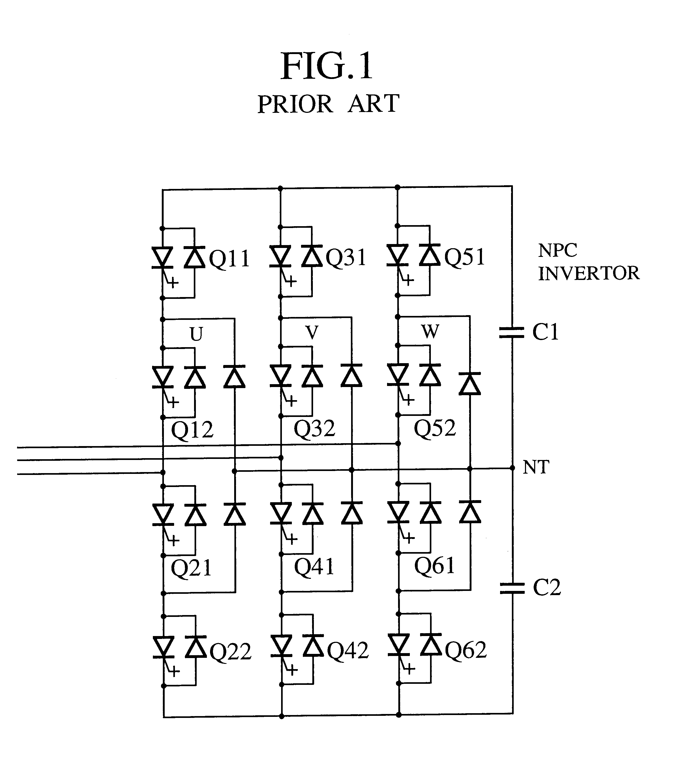
Although the inverters of the embodiment are 3-phase bridge inverters, the present invention may also employ single-phase-configuration 3-phase bridge inverters, NPC inverters capable of providing output voltages of multiple levels, etc. Although each inverter of the embodiment is of three phases, the present invention is applicable to M-phase inverters as shown in FIG. 10 as the second embodiment, where M is an optional number. In FIG. 10, each one of N (N is an optional number.) inverters is M-phase inverter, and each of M dividing voltage transformers 10-1 to 10-M has an N-leg iron core. A wiring is wound around each of N legs of the iron core. A load 3 is an M-phase load and supplied power from N inverters. of M-phase via M dividing voltage transformers 10-1 to 10-M each having N-legs.

As explained above, the power converting system of the first or second embodiment is parallel-multiplexed with voltage dividing transformers to produce no impedance with respect to a load current. ...

fourth embodiment

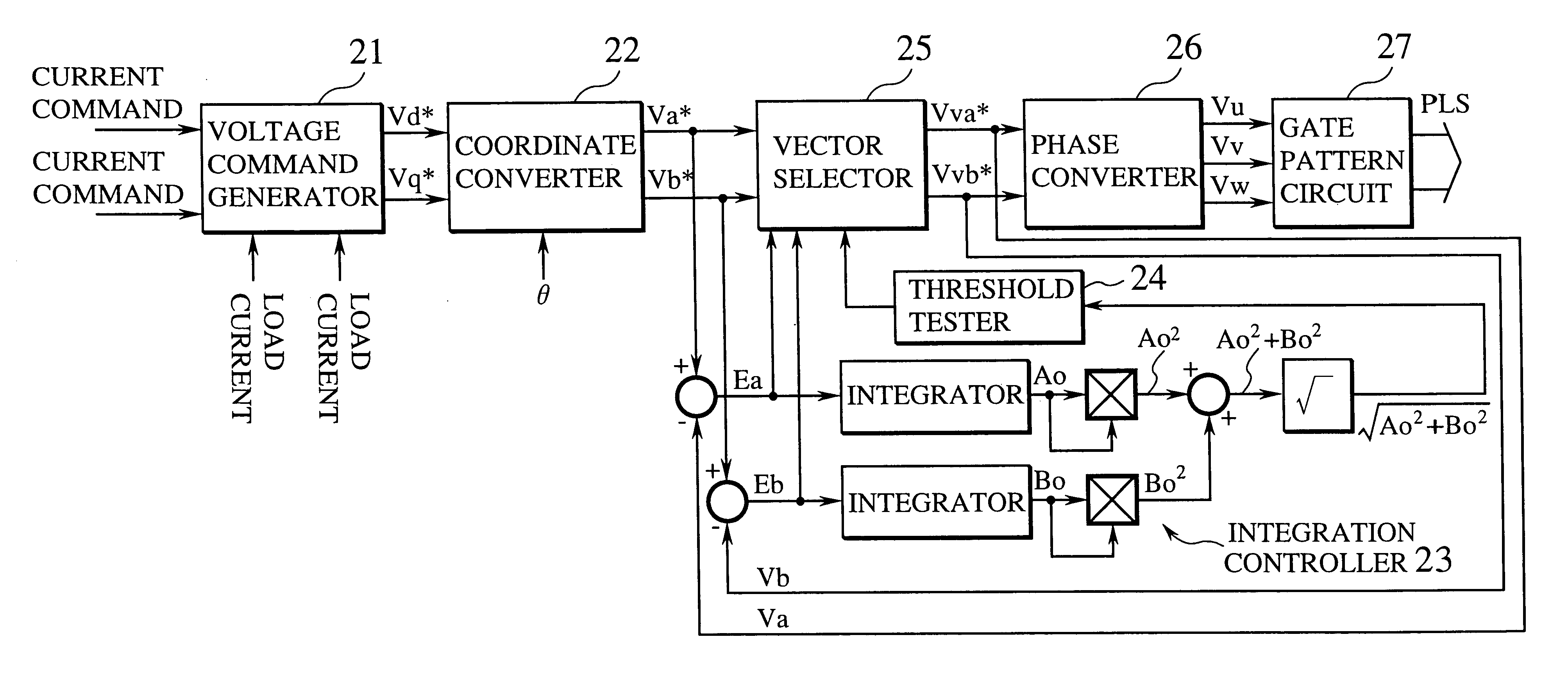
A controller for a power converting system according to the present invention will be explained with reference to FIG. 12. The controller controls a power converter such as an inverter of the power converting system. A voltage command generator 21 receives current commands and load currents, and issues voltage commands Vd* and Vq* for controlling actual currents. The voltage commands Vd* and Vq* that are on a rotating coordinate system that rotates in synchronization with a power source are converted by a coordinate converter 22 into voltage commands Va* and Vb* on a static coordinate system to calculate voltage command vectors. An integration controller 23 continuously integrates errors between the voltage commands Va* and Vb* and actual voltage command vectors Va and Vb. A threshold tester 24 determines the size of the integrated value. If the integrated value is above a threshold, a vector selector 25 selects an optimum switching state of the power converter and provides actual o...


PUM


Abstract

A power converting system has power converters for converting a direct current into an alternating current, a DC power source arranged on the DC side of the power converters, and voltage dividing transformers having windings whose first ends are connected to the power converters phase by phase and whose second ends are joined together and connected to a load phase by phase. Also provided is a controller for controlling the power converting system.

Description

1. Field of the InventionThe present invention relates to a power converting system multiplexed with voltage dividing transformers, the voltage transformers themselves, and a controller for controlling the power converting system so that the system may output sine waves having reduced harmonics.2. Description of the Prior ArtAn inverter for driving a motor at variable speeds generates AC voltages including direct currents. To smoothly drive the motor at variable speeds, the voltages generated by the inverter must be of sine waves involving reduced harmonics.To meet the requirements for outputting sine waves with reduced harmonics, NPC inverters (3-level inverters) are frequently employed for power converting systems.FIG. 1 shows a main circuit of an NPC inverter according to a prior art. The NPC inverter is capable of providing three phase-voltages and five line-voltages, to greatly reduce harmonics. The NPC inverter is characterized in that a voltage applied to each switching eleme...

Claims


Application Information

Patent Timeline
Patent Type & Authority Patents(United States)
IPC IPC(8): H02M7/48H02M7/505H02M7/49
CPCH02M7/49H02M2007/53876H02M7/53876H02M7/505
Inventor KITAHATA, TAKESHINISHIKAWA, HIROYUKIUCHINO, HIROSHIFUJITA, TAKASHIKAGEYAMA, TAKAHISAKANAI, TAKEOKAWAGUCHI, AKIRASAKAMOTO, TADAHIRO
Owner KK TOSHIBA
Why Eureka
Try Eureka