Isolation/damping mounting system for loudspeaker crossover network

Inactive Publication Date: 2001-01-09
SONY CORP +1
View PDF4 Cites 38 Cited by
  • Summary
  • Abstract
  • Description
  • Claims
  • Application Information

AI Technical Summary

Benefits of technology

The present invention provides an isolation grommet/ferrule mounting system for damping and acoustically isolating crossover components of a loudspeaker from the speaker cabinet and from airborne vibrations wi

Problems solved by technology

Loudspeaker crossover networks (the electrical filtering and equalization circuitry of a loudspeaker) are very prone to low level intermodulation distortion effects when exposed to vibrational energy.
Unfortunately, vibrational energy can be coupled from the air in the listening environment (i.e., the loudspeaker's output energy) into the networks.
Mounting the networks outside of the cabinet usually will require an additional enclosure and its associated external wiring complications and additional electrical connections, as well as signifi

Method used


Image

  • Isolation/damping mounting system for loudspeaker crossover network
  • Isolation/damping mounting system for loudspeaker crossover network
  • Isolation/damping mounting system for loudspeaker crossover network

Examples


Embodiment Construction

Preferred embodiments of the present invention will be described below by making reference to FIGS. 1 to 6(B) of the drawings.

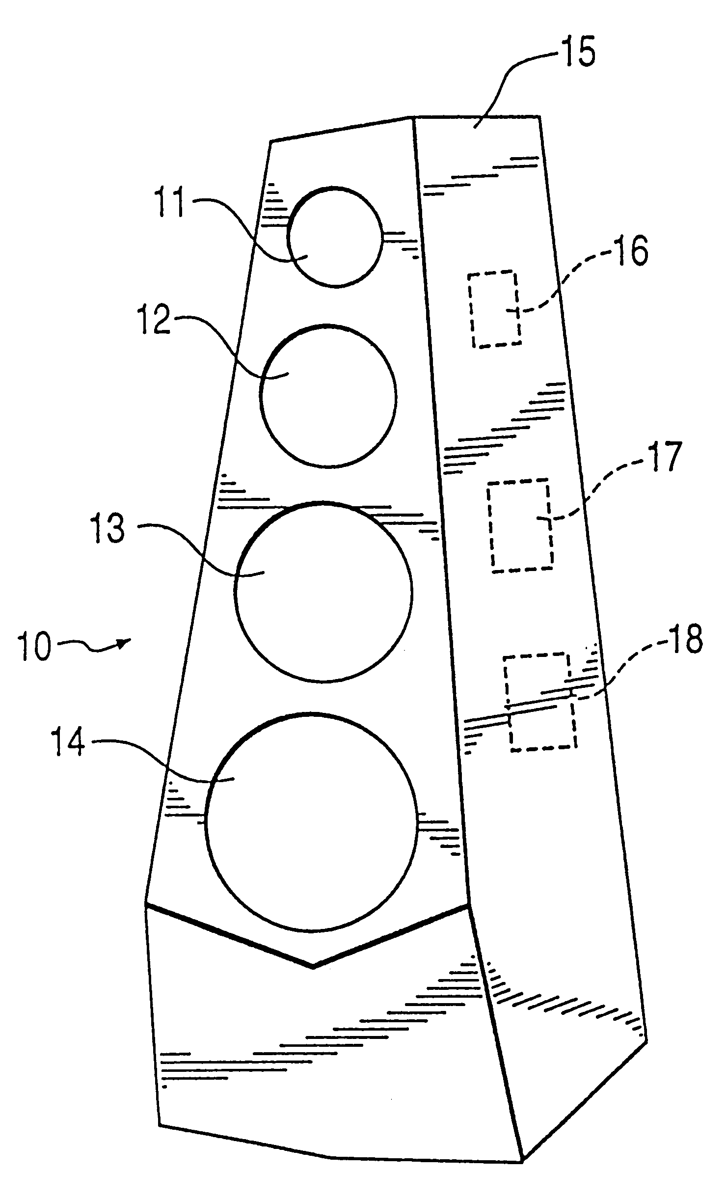
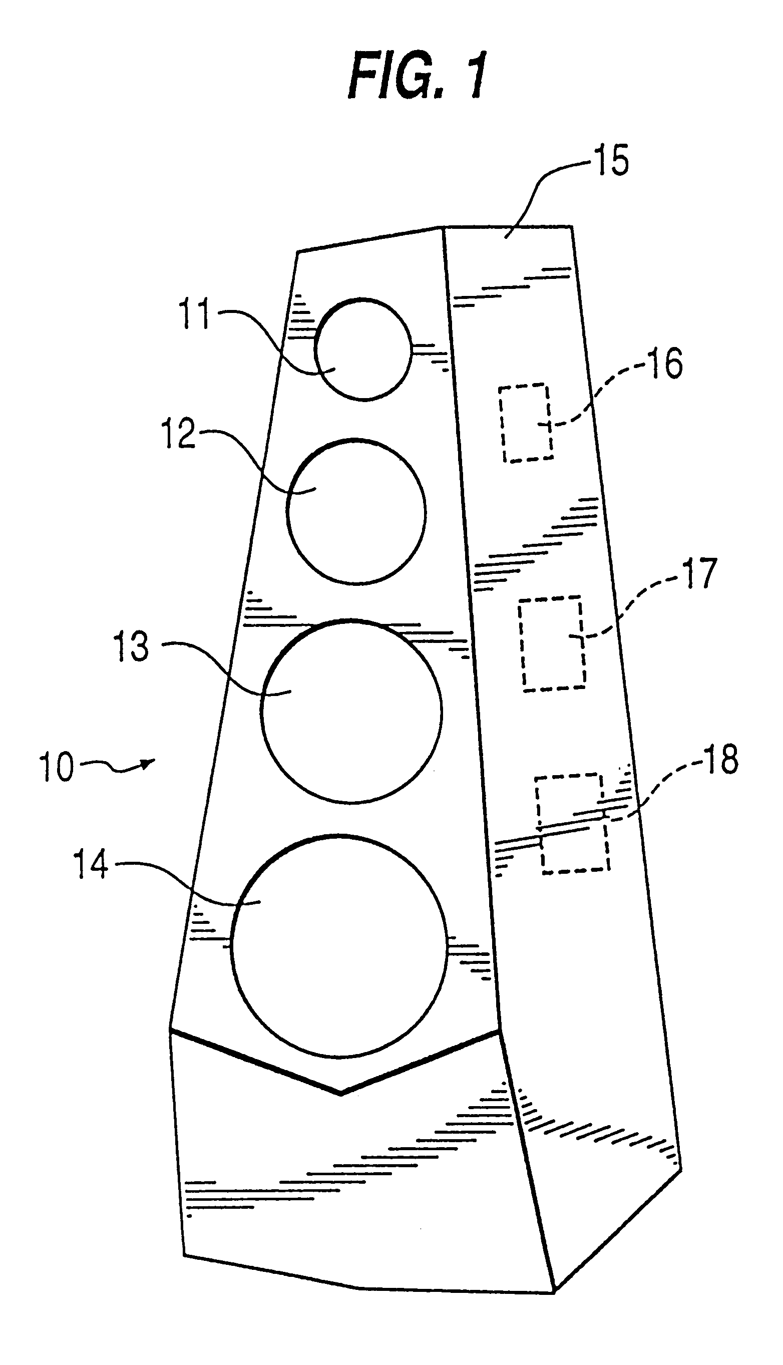
The present invention was developed for use in a high performance loudspeaker, such as the loudspeaker 10 shown in FIG. 1. The loudspeaker includes a plurality of speaker components 11, 12, 13, 14 (e.g., tweeter, midrange, woofer, etc.). The speaker components are mounted within a speaker cabinet 15, which also supports other electrical components, such as crossover networks 16, 17, 18. The crossover networks 16, 17, 18 provide electrical filtering and equalization of the speaker system. The crossover networks 16, 17, 18 each comprise a pc board or mounting board (if hard wired) having sensitive electronic components mounted thereon which are prone to low level intermodulation distortion effects when exposed to vibrational energy.

The mounting system of the present invention decouples the crossover networks 16, 17, 18 from the loudspeaker cabinet 15, thereby i...


PUM


Abstract

A mechanical mounting system and extensional damping technique for loudspeaker crossover networks. This system decouples the crossover network from the loudspeaker enclosure (cabinet), isolating it from any vibrational energy in the cabinet walls. In addition, an extensional damping material is applied to the crossover network to damp any vibrational energy which may be coupled from the surrounding air into the network. The mounting system can be used for mounting any sensitive electronic components within an enclosure to provide isolation from the walls of the enclosure and from surrounding or environmentally induced vibrational energy.

Description

1. Field of the InventionThe present invention relates generally to mechanical mounting arrangements and, in particular, to a mechanical mounting system and extensional damping technique for loudspeaker crossover networks.2. Description of the Relevant ArtLoudspeaker crossover networks (the electrical filtering and equalization circuitry of a loudspeaker) are very prone to low level intermodulation distortion effects when exposed to vibrational energy. This often becomes critical when the crossover networks are mounted within the loudspeaker cabinet where vibrational energy may be propagating freely though the cabinet walls and the interior air. Since most crossover networks are rigidly mounted to the cabinet walls, vibrational energy is directly coupled into the network. Energy coupled from the cabinet usually will travel though the network mounting screws, pc board or mounting board (if hard-wired) and into the electrical components themselves. It is also possible for vibrational ...

Claims


Application Information

Patent Timeline
IPC IPC(8): H04R1/02
CPCH04R1/02
Inventor ANAGNOS, DANIEL P.
Owner SONY CORP
Why Eureka
Try Eureka