In-cylinder direct-injection spark-ignition engine

Inactive Publication Date: 2001-01-16
NISSAN MOTOR CO LTD
View PDF3 Cites 41 Cited by
  • Summary
  • Abstract
  • Description
  • Claims
  • Application Information

AI Technical Summary

Benefits of technology

With such a helical intake port, air flow is controlled from just before intake-port valves so as to strengthen swirl airflow. However, the use of the helical port results in increased airflow resistance against incoming intake-air flow, thus reducing a charging efficiency of intake air (a decrease in induction efficiency at high engine speeds, i.e., a drop in engine performance at full throttle). In contrast to the above, if a direct-injection spark-ignition engine is designed with a pair of straight intake ports, adequate swirl flow cannot be produced, and thus there is a problem of piston-bowl wetting during a stratified combustion mode. As mentioned above, it is desirable to more highly reconcile lean or ultra-lean stratified charge combustion for low fuel consumption and homogeneous charge combustion for high power output. Accordingly, it is an object of the invention to provide a direct-injection spark-ignition engine which avoids the aforementioned disadvantages of the prior art.
In order to accomplish the aforementioned and other objects of the present invention, an in-cylinder direct-injection spark-ignition engine comprises a cylinder block having a cylinder, a piston movable through a stroke in the cylinder, a cylinder head on the piston, a pentroof combustion chamber recessed in a bottom of the cylinder head and having first and second shallow-angled surfaces, a pair of intake valves disposed in the first shallow-angled surface of the pentroof combustion chamber, a pair of exhaust valves disposed in the second shallow-angled surface of the pentroof combustion chamber, a pair of substantially straight intake ports, in which the pair of intake valves op

Problems solved by technology

However, the use of the helical port results in increased airflow resistance against incoming intake-air flow, thus reducing a charging efficiency of intake air (a decrease in induction efficiency at high engine speeds, i.e., a drop in engine performance at fu

Method used


Image

  • In-cylinder direct-injection spark-ignition engine
  • In-cylinder direct-injection spark-ignition engine
  • In-cylinder direct-injection spark-ignition engine

Examples


Example

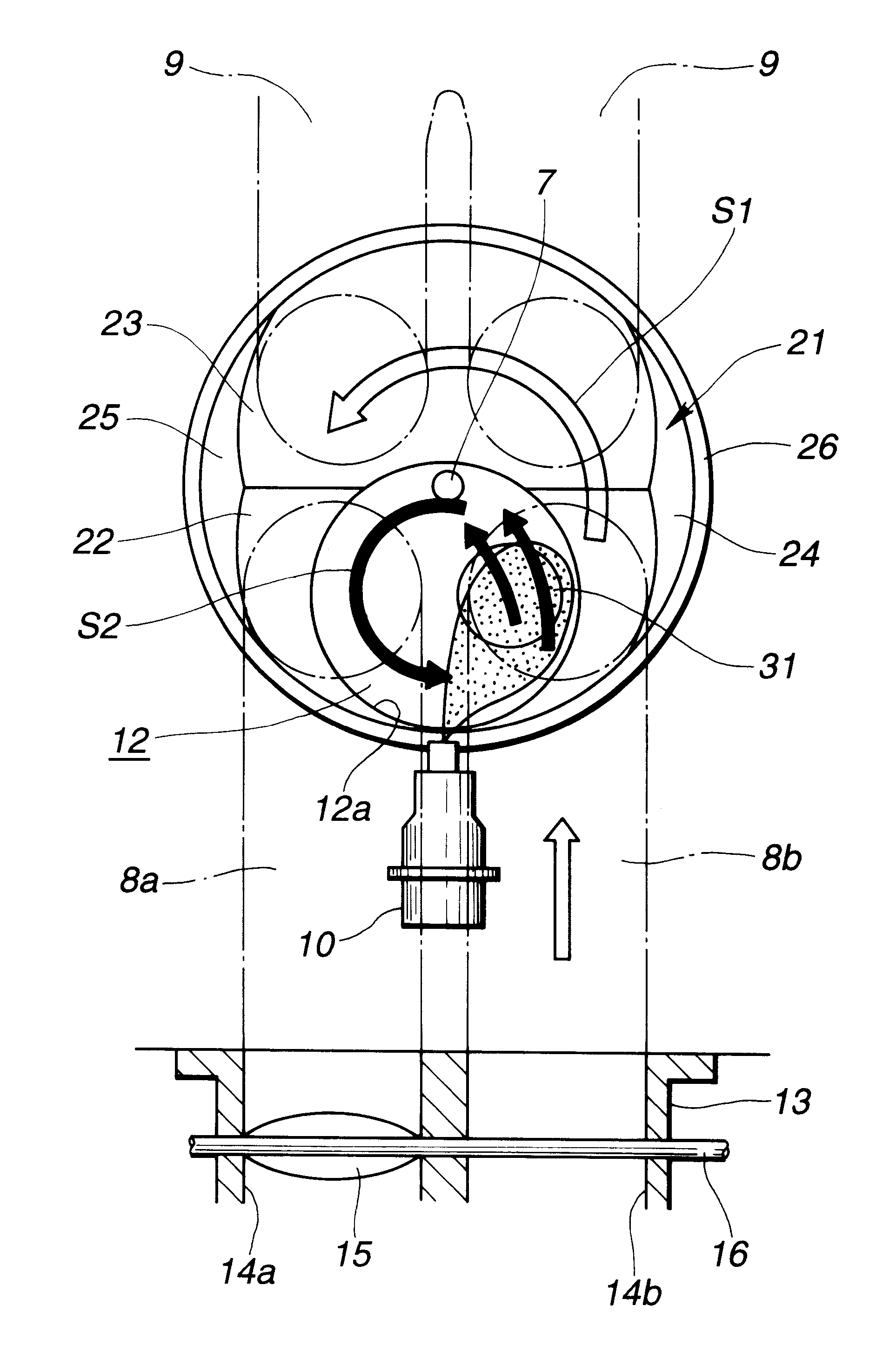
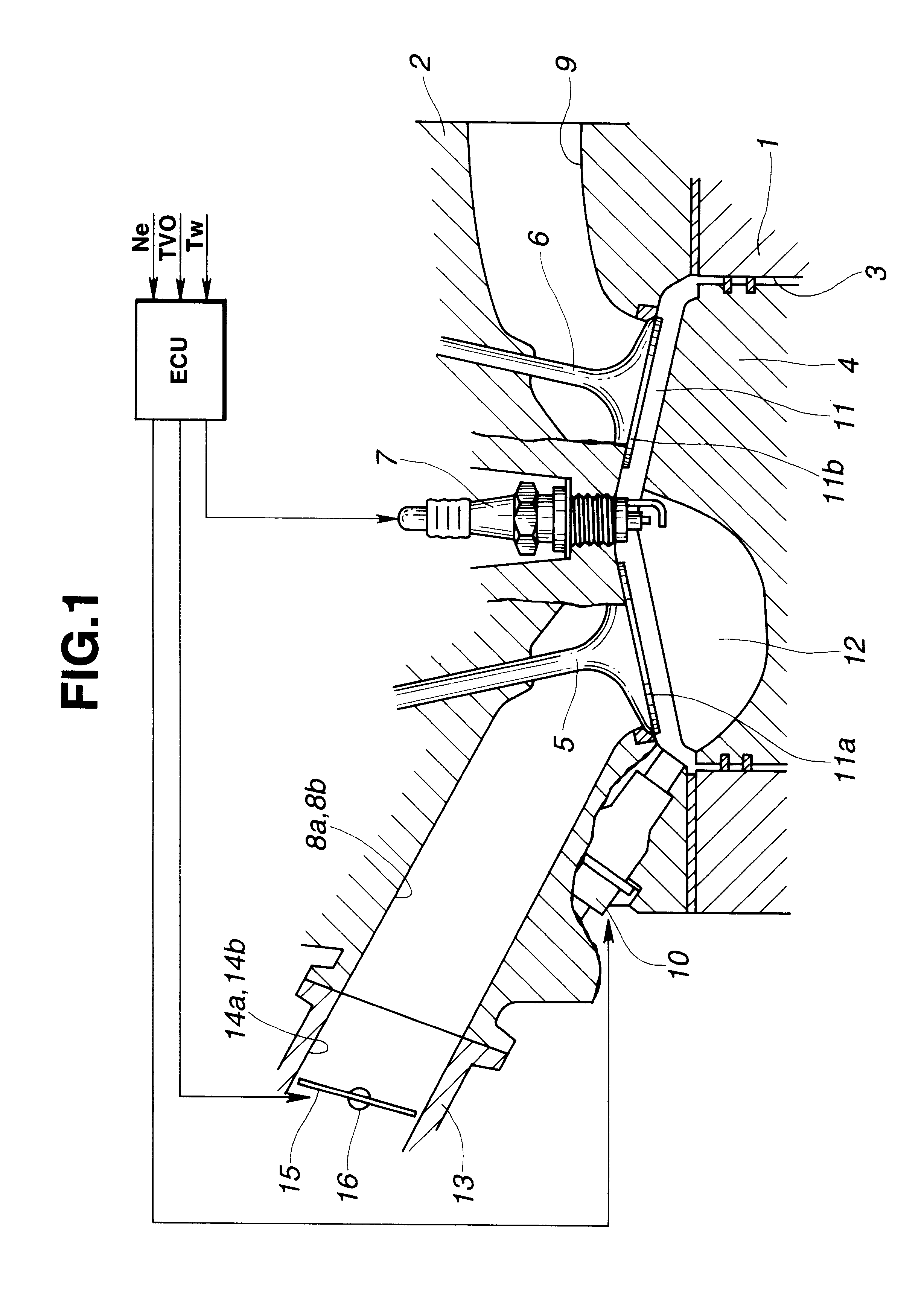
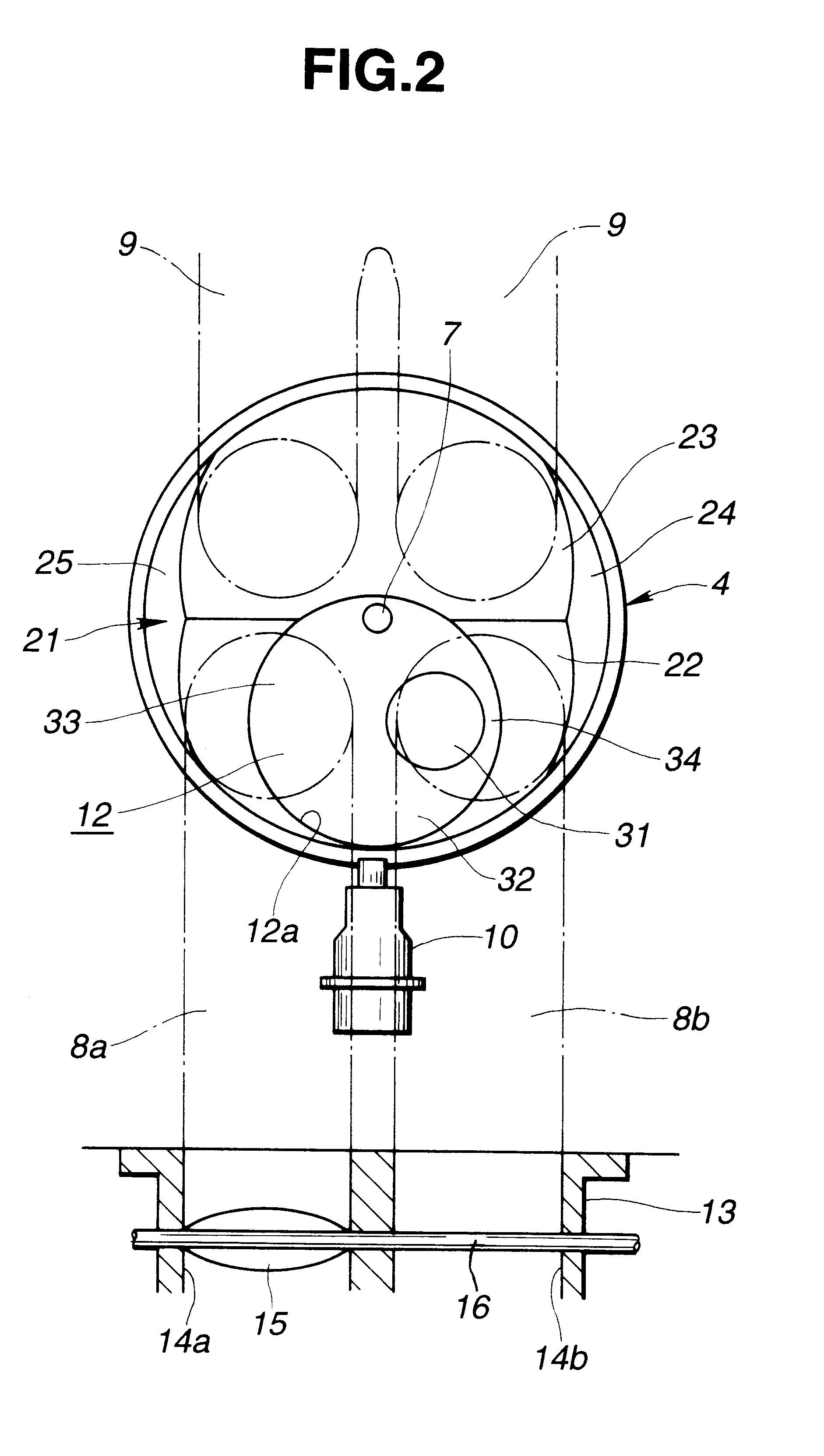
Referring now to the drawings, particularly to FIGS. 1 and 2, the in-cylinder direct-injection spark-ignition engine of the invention is exemplified in an in-line overhead-valve engine with a four-valve combustion chamber head. A plurality of engine cylinders 3 are arranged in one line in a cylinder block 1. A cylinder head 2 is mounted on the cylinder block 1 to enclose cylinder bores. A piston 4 is slidably fitted into the cylinder 3, and movable through a stroke in the cylinder. A pentroof combustion chamber 11 is formed or recessed in the bottom of the cylinder head 2 like a shallow angled hemisphere. As viewed from the longitudinal cross section shown in FIG. 1, a pair of intake valves (5, 5) are disposed in the left-hand shallow-angled surface 11a of the pentroof combustion chamber 11, whereas a pair of exhaust valves (6, 6) are disposed in the right-hand shallow-angled surface 11b. As clearly seen in FIGS. 1 and 2 in combination, a spark plug 7 is installed in the cylinder he...


PUM


Abstract

An in-cylinder direct-injection spark-ignition engine using at least a homogeneous combustion mode and a stratified combustion mode and equipped with a pentroof combustion chamber head having first and second shallow-angled surfaces, comprises intake valves disposed in the first shallow-angled surface, exhaust valves disposed in the second shallow-angled surface. A pair of substantially straight intake ports are formed in the cylinder head. A tumble-and-swirl control valve is disposed in a first intake port of the substantially straight intake ports for adjusting the amount of intake air passing through the first intake port. A piston crown comprises an intake-valve side inclined surface generally parallel to the first shallow-angled surface, an exhaust-valve side inclined surface generally parallel to the second shallow-angled surface, and a piston bowl having an opening of a substantially complete round and arranged in an eccentric position with respect to the outside circle of the upper portion of the piston toward the intake valves. The piston bowl has a deeply-recessed bowl cavity. The deeply-recessed bowl cavity is arranged eccentrically to the opening of the piston bowl toward a second intake port of the substantially straight intake ports.

Description

BACKGROUND OF THE INVENTION1. Field of the InventionThe present invention relates to an in-cylinder direct-injection spark-ignition engine with an electronic concentrated engine control system, employing a variable swirl-and-tumble control mechanism and an electronically-controlled fuel-injection system used to switch between a homogeneous combustion mode using tumble airflow and a stratified combustion mode using swirl airflow.2. Description of the Prior ArtIn recent years, there have been proposed and developed various in-cylinder direct-injection spark-ignition engines in which fuel is injected directly into the engine cylinder. The direct-injection spark-ignition engine uses at least two combustion modes, namely an early injection combustion mode or a homogeneous combustion mode where fuel-injection early in the intake stroke produces a homogeneous air-fuel mixture, and a late injection combustion mode or a stratified combustion mode where late fuel-injection delays the event un...

Claims


Application Information

Patent Timeline
IPC IPC(8): F02B23/10F02B31/08F02B17/00F02B31/00F02B75/00F02F1/42F02F1/24F02B75/12F02B23/08F02F3/26
CPCF02B17/005F02B23/104F02B31/085F02B2023/106F02B2023/108F02B2031/006F02B2075/125F02B2275/48F02F1/4214F02F2001/241F02F2001/245Y02T10/125Y02T10/146Y02T10/123Y02T10/12
Inventor IRIYA, YUUICHIAOYAMA, TAKASHIARAMAKI, KAZUYOSHI
Owner NISSAN MOTOR CO LTD
Why Eureka
Try Eureka