Pressure sensor

a pressure sensor and sensor technology, applied in the field of pressure sensors, can solve problems such as the fear of deviation in the pressure being sensed

Inactive Publication Date: 2001-01-23
FUJIKOKI CORP
View PDF11 Cites 59 Cited by
  • Summary
  • Abstract
  • Description
  • Claims
  • Application Information

AI Technical Summary

Benefits of technology

Even further, the object of the present invention is to provide a pressure sensor enabling the sensor element and the housing to be formed of different metallic materials, when welding and supporting the sensor element.
According to the pressure sensor mentioned above, the holder being provided not only enables to define a reference pressure space, but it also works to prevent the direct airtight welding of the heading and the housing, which makes it possible to select the material of each member optionally, and therefore, different kinds of metal may be used to form the base plate and the housing.

Problems solved by technology

When the prior art sensor was used in the refrigeration cycle of an air conditioner mounted on vehicles, the variation in the atmospheric pressure based on the difference in altitude had effects on the sensing of pressure, and there was fear that a deviation may be generated in the pressure being sensed.

Method used


Image

  • Pressure sensor
  • Pressure sensor
  • Pressure sensor

Examples


second embodiment

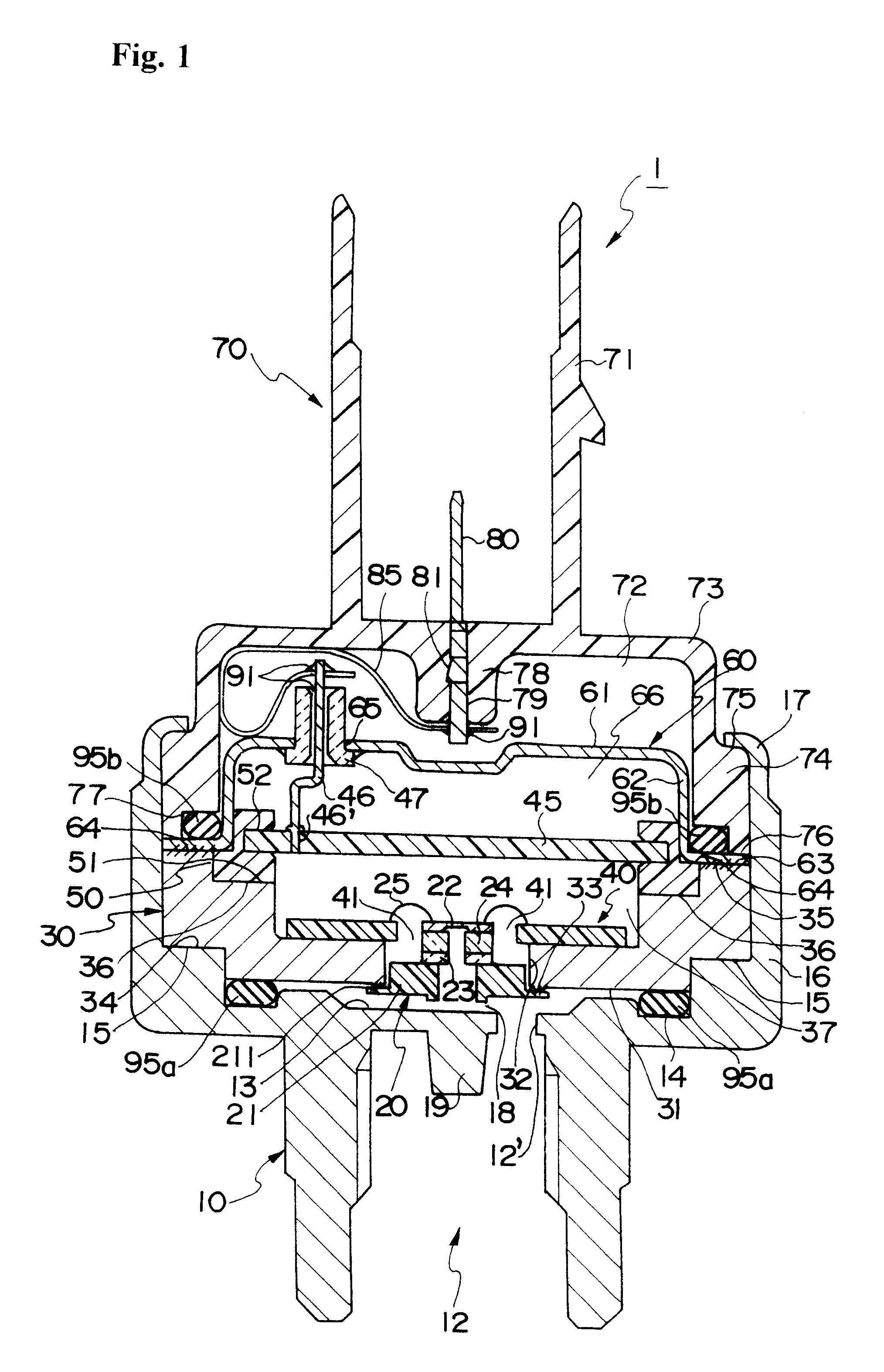
the pressure sensor according to the present invention will now be explained with reference to FIG. 2. FIG. 2 is a vertical cross-sectional view showing the structure of the pressure sensor according to the second embodiment.

The pressure sensor 1 according to the second embodiment of the present invention differs from the pressure sensor 1 shown in FIG. 1 in that the circuit board is a single circuit board 40 instead of the first circuit board 40 and the second circuit board 45, the structure for supporting the sensor element is simplified, the pressure case 60 is omitted, and the connection between the circuit board 40 and the terminal 80 is simplified.

The pressure sensor 1 according to the second embodiment of the invention basically comprises a housing 10, a sensor element 20, and a holder 30 for maintaining the sensor element 20 to an airtight condition.

The pressure sensor 1 is formed so that the container formed of the housing 10 and a connector case 70 stores a pressure sensor...

third embodiment

Next, the pressure sensor according to the present invention will be explained with reference to FIGS. 3 through 7. FIG. 3 is a vertical cross-sectional view showing the structure of the pressure sensor from the front side. FIG. 4 is a side view of the pressure sensor of FIG. 3 taken from the right side, where the connector case is removed and one portion of the rising portion of the housing is taken away. FIG. 5 is an explanatory view showing the shape of the terminal holder to be used in the present embodiment, and it is a schematic view of the terminal holder shown in FIG. 4 which is turned upside down and seen from the upper oblique position. FIGS. 6 and 7 are a view of the pressure sensor shown in FIGS. 3 and 4 seen from the upper side. FIG. 6 is a view of the cross-section taken at line A--A of FIG. 3 seen from the upper direction, and FIG. 7 is a view of the cross-section taken at line B--B of FIG. 3 seen from the upper direction.

The pressure sensor 1 according to the third e...

fourth embodiment

the pressure sensor according to the present invention will be explained with reference to FIGS. 8 and 9. FIG. 8 is a vertical cross-sectional view showing the structure of the pressure sensor from the front, and FIG. 9 is a side view showing the pressure sensor from the right side of FIG. 8. In FIG. 9, the connector case is removed, and an area in the rising portion of the housing is cut off.

The pressure sensor according to the present embodiment only differ from the pressure sensor of the third embodiment in the shape of the terminal holder 180, and the other structures are substantially the same. Therefore, the explanation on the structures other than the terminal holder 180 are omitted.

The terminal holder 180 of the pressure sensor 1 according to the present embodiment differs from that of the third embodiment in that a penetrating hole 186 for guiding the lead is used instead of the lead guide groove 184 of the terminal holder 180, and that an opening 82 is equipped instead of ...


PUM

PropertyMeasurementUnit
sensing pressureaaaaaaaaaa
piezoresistance effectaaaaaaaaaa
pressureaaaaaaaaaa

Abstract

A pressure sensor 1 comprises a metallic housing 10 having a space 18 communicated to a pressure detection space and a thin rising portion 17 formed on the upper end of the peripheral area, a sensor element 20, a sensor element holder 30, a metallic pressure case 60 having a ceiling portion 61, and a connector case 70 formed of an insulating material, wherein a collar portion 211 of a base plate 21 of the sensor element 20 including a pressure sensing element 22 is contacted to an annular protrusion 33 positioned around the opening 32 of the sensor element holder 30, and the collar portion 211 is airtightly welded to the annular protrusion 33 by projection welding. Further, the collar portion 63 on the pressure case 60 and the peak surface 35 of the holder 30 is airtightly welded by an electron beam welding. The airtight interior space defined by the sensor element 20, the sensor element holder 30 and the pressure case 60 is utilized as the reference pressure space.

Description

The present invention relates to a pressure sensor, and particularly, to a pressure sensor having a housing for storing a sensor element and a connector case, the sensor adopting an absolute pressure method or a sealed gauge pressure method, which is free from any effects caused by electromagnetic noise.Further, the present invention relates to a pressure sensor wherein the sensor element being stored inside a housing is welded thereto with advantageous airtightness.DESCRIPTION OF THE RELATED ARTA strain gage-type semiconductor pressure sensor of the prior art is disclosed, for example, in Japanese Laid-Open Patent Publication No. 7-29435. In this prior art pressure sensor, a pressure sensor element (pressure sensor chip) is mounted on a concave formed on a body (corresponding to the housing of the present invention) through a metallic base (corresponding to the base plate of the present invention) and a glass base. Pressure is impressed to the pressure sensor element through a pene...

Claims


Application Information

Patent Timeline
Patent Type & Authority Patents(United States)
IPC IPC(8): G01L9/00G01L9/04H01L29/84
CPCG01L19/0038G01L19/0084G01L19/147H01L2224/48091H01L2224/73265H01L2924/00014H01L29/84
Inventor SASAKI, KEIJIMIYANO, JUN-ICHISAWADA, AKIRA
Owner FUJIKOKI CORP
Why Eureka
Try Eureka