Transmitting and receiving antenna voltage standing wave ratios measuring circuit of base station in mobile communication system

a technology of mobile communication system and which is applied in the field of mobile communication system, can solve the problems of inability to accurately measure the voltage standing wave ratio of transmitting and receiving antennas, the inability to measure the transmitting power and receiving power of each frequency band,

Inactive Publication Date: 2001-01-23
LG ERICSSON
View PDF3 Cites 70 Cited by
  • Summary
  • Abstract
  • Description
  • Claims
  • Application Information

AI Technical Summary

Problems solved by technology

According to the transmitting and receiving antenna VSWR measuring circuits of the base station in the conventional mobile communication system, however, the transmitting power and receiving power of each frequency band cannot be measured in a multi-frequency allocation system, and the transmitting and receiving antenna VSWRs cannot be accurately measured when a noise signal exists in an adjacent frequency band.

Method used


Image

  • Transmitting and receiving antenna voltage standing wave ratios measuring circuit of base station in mobile communication system
  • Transmitting and receiving antenna voltage standing wave ratios measuring circuit of base station in mobile communication system
  • Transmitting and receiving antenna voltage standing wave ratios measuring circuit of base station in mobile communication system

Examples


Embodiment Construction

Reference will now be made in detail to the preferred embodiments of the present invention, examples of which are illustrated in the accompanying drawings.

With reference to the attached drawings, a preferred embodiment of the present invention is described below in detail.

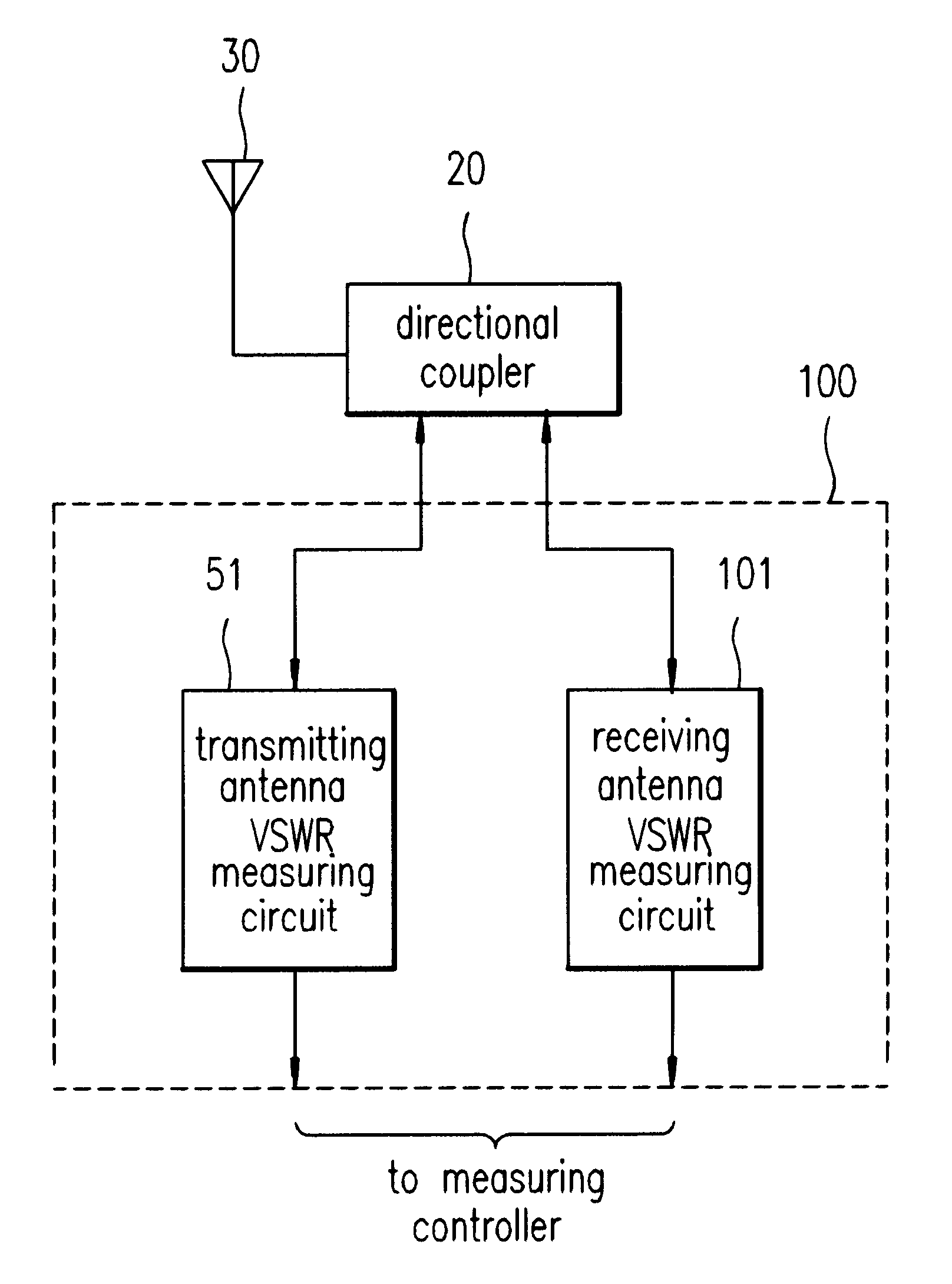
As shown in FIG. 3, the transmitting and receiving antenna VSWRs measuring circuit according to the present invention includes: a transmitting antenna VSWR measuring circuit 51 for variable-attenuating and detecting transmitting signals and sending a transmitting signal strength to a measuring controller which measures transmitting power and reflection power; and a receiving antenna VSWR measuring circuit 101 for variable-attenuating and detecting receiving signals and sending a receiving signal strength to a measuring controller which measures receiving power and reflection power.

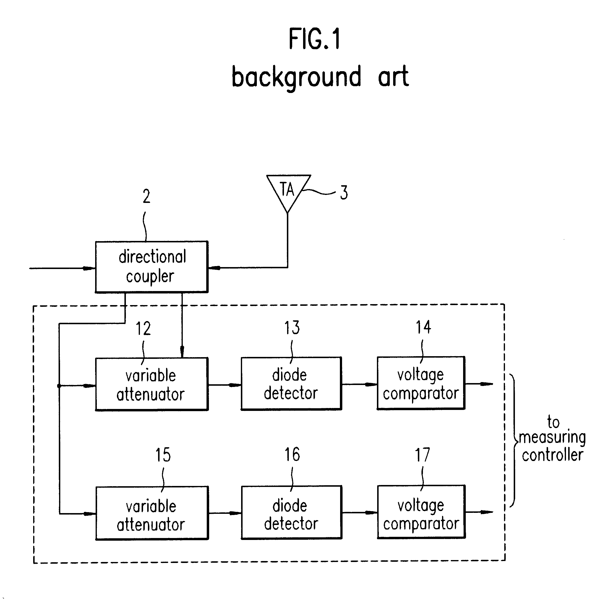
Referring to FIG. 4, the transmitting antenna VSWR measuring circuit 51 includes: variable attenuators 52, 53, and 54 coupled to a direc...


PUM


Abstract

A transmitting and receiving antenna VSWRs (voltage standing wave ratio) measuring circuit of a base station in a mobile communication system comprises: transmitting and receiving antennas for transmitting and receiving a radio frequency signal of a predetermined frequency band in a mobile communication system; transmitting antenna VSWR measuring means for variable-attenuating and detecting a transmitting signal received from the transmitting antenna and sending a transmitting signal strength to a measuring controller whereby to measure transmitting power and reflected power; and receiving antenna VSWR measuring means for variable-attenuating and detecting a receiving signal received from the transmitting antenna and sending a receiving signal strength to a measuring controller whereby to measure receiving power and reflected power.

Description

1. Field of the InventionThe present invention relates to a mobile communication system, and, particularly, to a circuit for measuring voltage standing wave ratios (VSWR) of transmitting and receiving antennas in a base station.2. Discussion of Related ArtVSWR of a transmitting / receiving antenna of a base station indicates that the ratio of the maximum value and minimum value of a standing wave is 1 in matching state, the standing wave being generated by interference of an incident wave and reflected wave when connecting a load impedance in a transmission line. If the standing wave does not equal to a characteristic impedance in a limited transmission line, some of the incident waves are reflected thereby to generate the reflected waves. The VSWR influences the performance of the transmitting / receiving antenna of the base station. Therefore, it is necessary to accurately measure the VSWR and implement the matching state.FIGS. 1 and 2 are block diagrams respectively showing transmitt...

Claims


Application Information

Patent Timeline
Patent Type & Authority Patents(United States)
IPC IPC(8): H04B17/00H04B1/60G08C17/00
CPCH04B17/318H04B17/0085G08C17/00H04B1/60
Inventor JEONG, IL YONG
Owner LG ERICSSON
Why Eureka
Try Eureka