Specifying complex device configeration through use characteristics

a technology of complex devices and use characteristics, applied in the field of customized complex device configurations, can solve the problems of limited customer choice to a limited set of configurations, unsatisfactory or satisfied customer wants and needs that vary from these configurations, and difficult direct customer selection of components

Inactive Publication Date: 2001-01-23
IBM CORP
View PDF4 Cites 13 Cited by
  • Summary
  • Abstract
  • Description
  • Claims
  • Application Information

AI Technical Summary

Problems solved by technology

More generally, the customer evaluation criteria will depend on combinations of the components making direct customer selection of the components problematic.
More subtly, it is also predicated on the presumed high cost of engineering a working product and of the lead time associated with offering such a product.
First is the obvious limitation of customer choice to a limited set of configurations.
Customer wants and needs that vary from these configurations are either unsatisfied or satisfied through a costly special bid process replicating much of the original product development cycle.
The...

Method used


Image

  • Specifying complex device configeration through use characteristics
  • Specifying complex device configeration through use characteristics
  • Specifying complex device configeration through use characteristics

Examples


Embodiment Construction

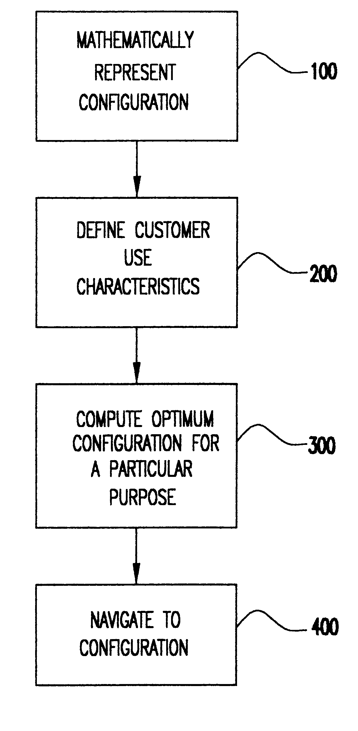
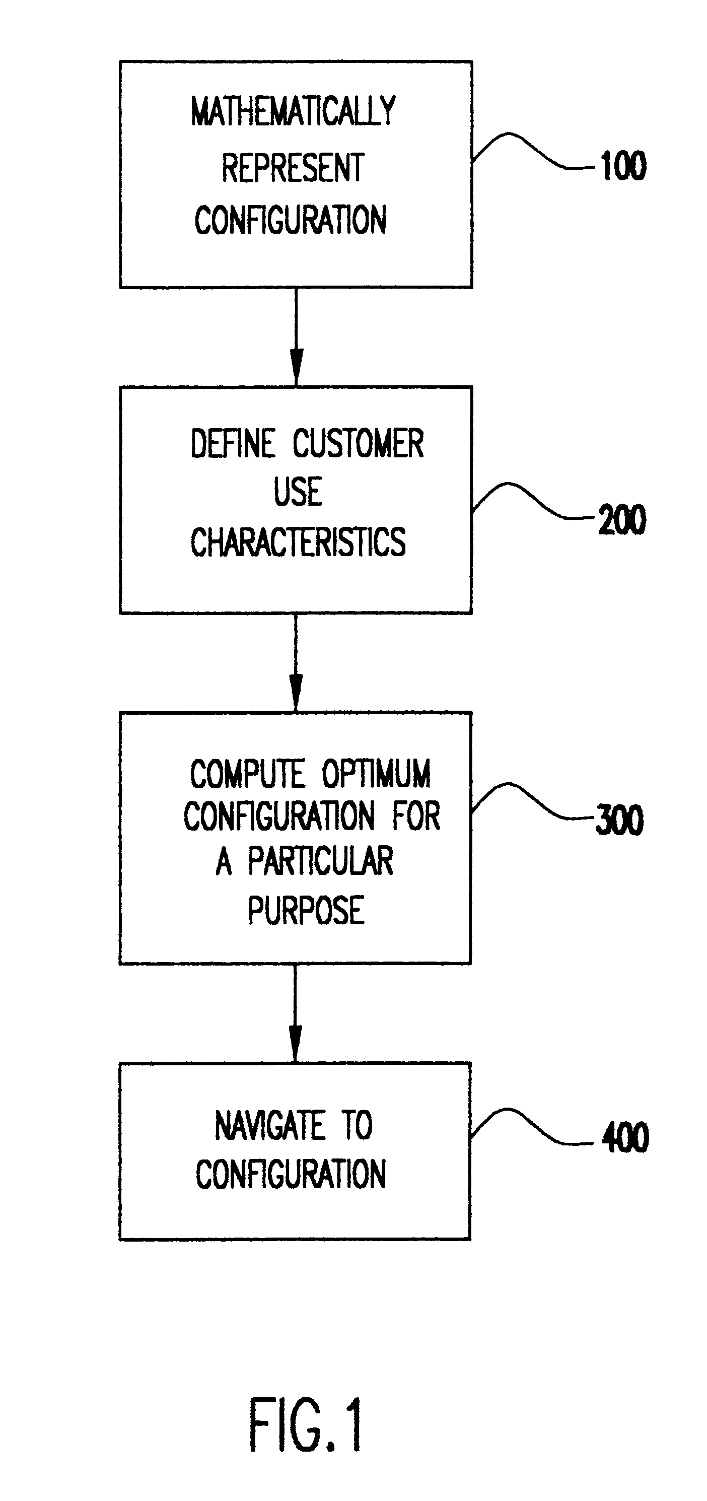
Referring now to the drawings, and more particularly to FIG. 1, there is shown a flow diagram that provides an overview of the method of the present invention. Each block will subsequently be discussed in further detail in the specification. In block 100, the configuration is represented mathematically. In block 200, customer use characteristics are defined, where there is a mapping from component set to customer use. In block 300, an optimum configuration for a particular purpose is computed from the use characteristics, where there is a mapping from customer use to component set. Finally, in block 400, the configuration may be navigated, where a configuration through use characteristics is selected.

Mathematical Representation

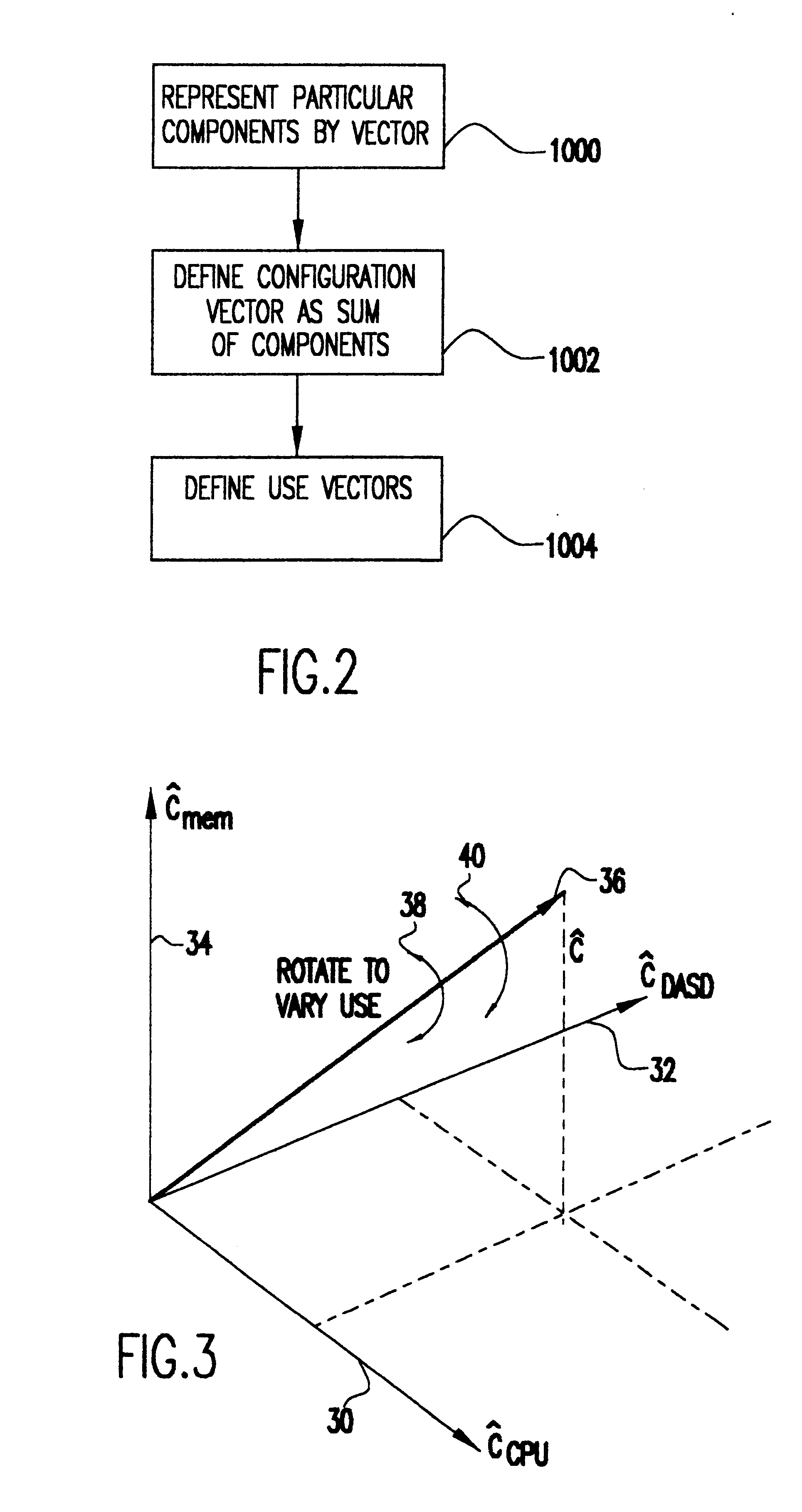
Referring now to FIG. 2, which shows block 100 in further detail, block 1000 shows that particular components are represented by a vector. In particular, the vector is defined as c.sub.ij =.vertline.c.sub.ij.vertline.c.sub.i, where the direction, c.sub.i, repr...


PUM


Abstract

A method for relating a specific configuration of complex units constructed from components with standardized interfaces to the user characteristics of the complete unit. The invention provides a bidirectional mapping between a statement of value to the user through the computation of fitness for a particular purpose (or "use") and a technical configuration. The customer can be presented with a system optimized for a particular use at a particular price point. Through presenting a range of systems around the optimum point and presenting the strength of the system for a variety of uses as the customer varies components, a wide range of customer choice is presented within an understandable range of choices. Each component is characterized by a strength parameter, and the set of components is arranged as a vector. This configuration vector can then be projected on a vector representing a standard use. Particular configuration vectors are characterized by a direction and a magnitude. The magnitude represents an overall strength of a configuration related to the performance or capacity of its individual components. The direction of a general configuration vector can be compared to the direction of a configuration tuned for a particular purpose or use. Similarly, a configuration can be constructed by scaling its magnitude along the direction defined by a tuned configuration and varying the direction to optimize among various uses.

Description

1. Field of the InventionThe present invention generally relates to specifying customized complex device configurations for manufacture and, more particularly, to relating a specific configuration of complex units constructed with components with standardized interfaces to use characteristics of the complete unit.2. Background DescriptionDetermining the configuration of a mass customized unit to suit a particular customer can be divided into three steps. First is establishing what the customer wants and needs, then relating that to a specific configuration of the mass customized unit, and finally establishing that the configuration can be built. The problem solved by the subject invention is that of enabling the customers to work directly with terms and quantities of value to them while simultaneously producing a configuration of technical components suitable for manufacturing. The assumption of a mass customized unit implies that in the predominance of cases the actual customer der...

Claims


Application Information

Patent Timeline
IPC IPC(8): G06Q10/00G06Q10/08
CPCG06Q10/087
Inventor CASWELL, NATHAN S.NIGAM, ANIL
Owner IBM CORP
Why Eureka
Try Eureka