Power and data network system media architecture

a network system and data network technology, applied in the field of network systems, can solve the problems of inconvenient installation of trunk cables at each device node, general unsuitability of cables for and inability to meet the needs of industrial power levels and distances

Inactive Publication Date: 2001-01-30
ALLEN-BRADLEY CO LLC
View PDF47 Cites 39 Cited by
  • Summary
  • Abstract
  • Description
  • Claims
  • Application Information

AI Technical Summary

Problems solved by technology

However, such cables are generally unsuitable for industrial power levels and distances.
While such networks provide excellent data transmission capabilities as well as enable devices to be powered through a single trunk cable, they are not without drawbacks.
For example, the installation of the trunk cable at each device node may be a relatively time-consuming task, typically requiring each conductor to be separately wired to the node connector.
Moreover, because the trunk cable is shielded and conductors are wound or twisted within the cable to reduce the effects of internal and external noise, alternative attachment techniques, such as insulation displacement technology, are generally not readily applicable to the trunk cable.
While the foregoing structure offers the facility of insulation displacement technology for assembly of the node connectors to the trunk cable, it too has significant drawbacks.
Also, because the cable is asymmetrical, connectors can be placed on one side of the cable only, reducing the flexibility of the system installation.
If the cable jacket fails to sufficiently heal itself, the reliability of the network, including both power and data transmission, is jeopardized.
Furthermore, where a device cable style needs to be changed, the entire connector is typically replaced, reducing the flexibility of the media system and imposing further costs on the system user.

Method used


Image

  • Power and data network system media architecture
  • Power and data network system media architecture
  • Power and data network system media architecture

Examples


Embodiment Construction

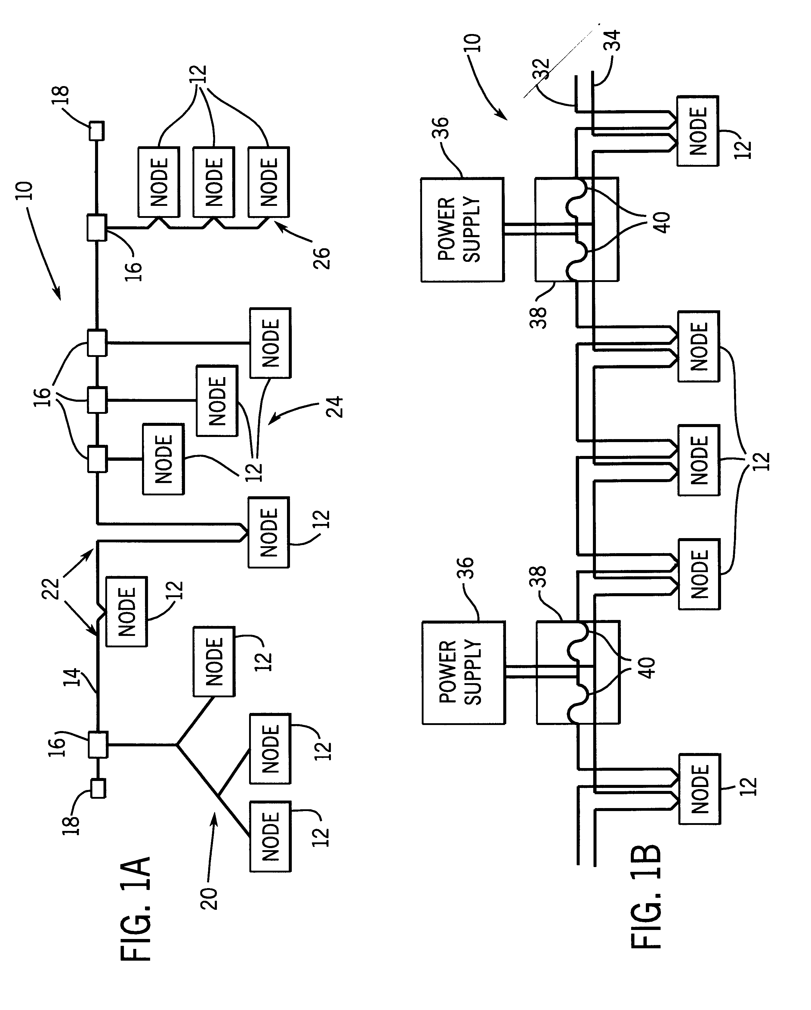
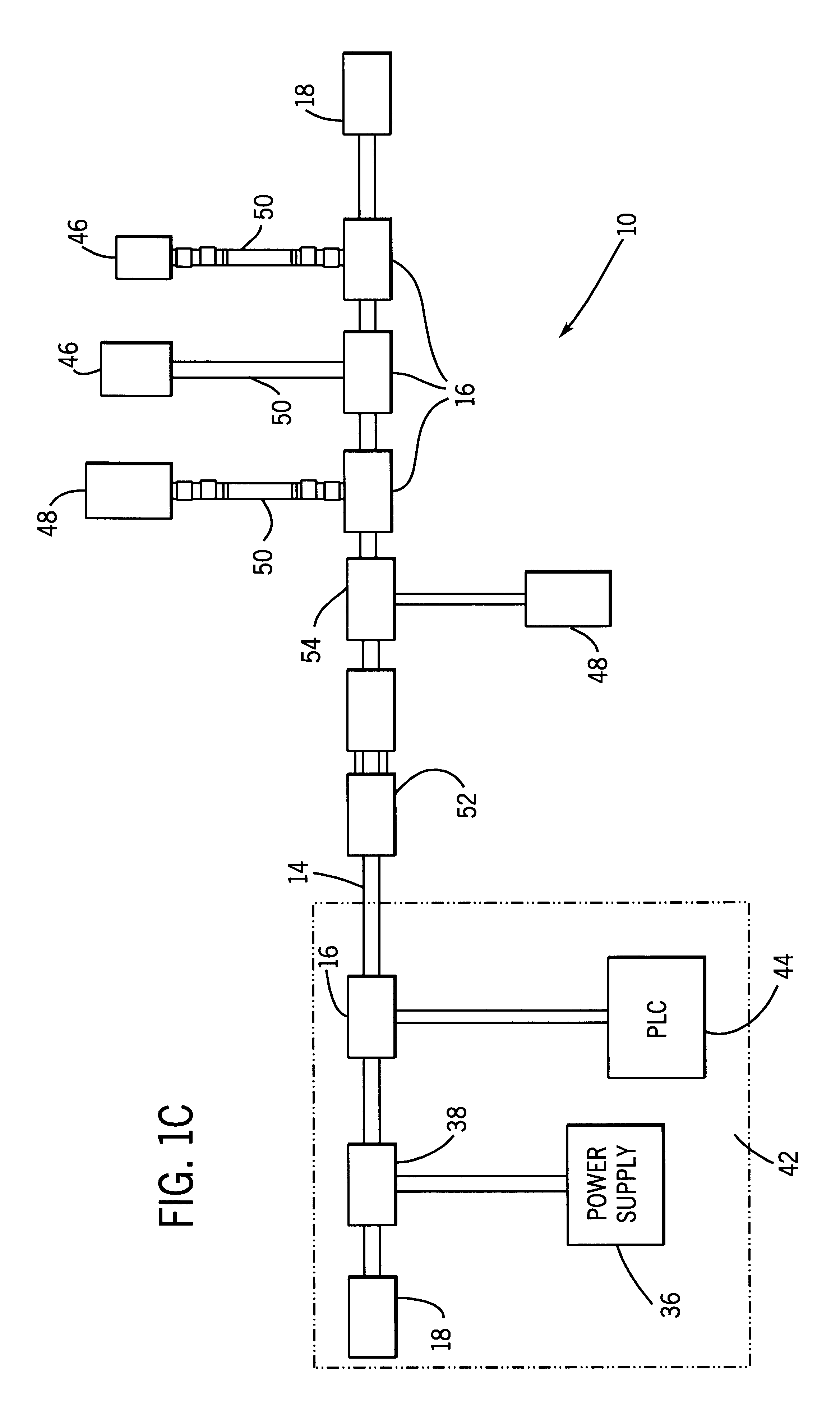
Turning now to the drawings, and referring first to FIG. 1, a data and power network is illustrated diagrammatically and designated generally by the reference numeral 10. The network includes a plurality of device nodes 12 coupled to one another via a trunk cable 14. Each device node receives power and data signals from cable 14 via a modular connector 16. At ends of cable 14 terminators 18 are provided for capping the cable ends and electrically terminating the signal conductors of the cable.

Each device node 12 will typically include a networked sensor or actuator unit, as will be appreciated by those skilled in the art. Depending upon the particular application in which network 10 is installed, nodes 12 may include such devices as push-button switches, proximity sensors, flow sensors, speed sensors, actuating solenoids, electrical relays, and so forth. The nodes 12 may be coupled to the network cable 14 in a variety of topologies, including "branch drop" structures 20, "zero drop"...


PUM


Abstract

A network system is provided for transmitting electrical power and data signals between a plurality of device nodes. The system includes a trunk cable in which a pair of dedicated power conductors and a pair of dedicated signal conductors are embedded in an insulative cover. Modular connectors are electrically coupled to the cable conductors at each device node. Each connector includes a base module and an interface module. The base module is attached to the cable via insulation piercing members and thereafter remains resident on the cable. The interface module is mated with the base module and serves to transmit power and data signals between the base module and a networked device. Several types of interface modules may be utilized interchangeably to permit the base module and cable to accommodate various types of devices and device drop cables.

Description

1. Field of the InventionThe present invention relates generally to network systems for transmitting power and data between device nodes. More particularly, the invention relates to a system media architecture incorporating modular connector devices coupled to a shared network conductor cable via insulation displacement members, permitting devices coupled at each connector node to draw both power and data from the cable.2. Description of the Related ArtA variety of control systems are known and are presently used in industry for communicating control and feedback signals between remote controllers, sensors and actuators. In a typical application, a process, such as a manufacturing or assembly line, will include a number of sensors for providing information relating to the manufacturing process, such as speeds of conveyors, speeds of motors, temperatures, pressures, feed rates, fluid levels, logical states of switches, and so forth. The sensed information is transmitted from the sens...

Claims


Application Information

Patent Timeline
Patent Type & Authority Patents(United States)
IPC IPC(8): H01R4/24H01R12/67H01R12/77
CPCH01R4/2408H01R12/675H01R12/778
Inventor ADAMS, SHAWN L.BRANDT, DAVID D.LOUNSBURY, ROBERT E.MACKEY, DENNIS C.MCLAUGHLIN, STEVEN R.MILLER, RICHARD F.TAYLOR, BRIAN J.
Owner ALLEN-BRADLEY CO LLC
Why Eureka
Try Eureka