Power conversion apparatus and air conditioner using the same
Inactive Publication Date: 2001-01-30
KK TOSHIBA
View PDF10 Cites 27 Cited by
Summary
Abstract
Description
Claims
Application Information
AI Technical Summary
This helps you quickly interpret patents by identifying the three key elements:
Problems solved by technology
Method used
Benefits of technology
Benefits of technology
The present invention has been made to solve the above drawbacks, and has as its object to provide a power conversion apparatus capable of increasing the power factor of the power supply and making the harmonic component of the power supply match or very closer to the IEC standard.
It is another object of the present invention to provide an air conditioner using the power conversion apparatus capable of increasing the power factor of the power supply and making the harmonic component of the power supply match or very closer to the IEC standard.
Problems solved by technology
In this case, however, the apparatus becomes bulky.
For this reason, the rotational speed and the like of the compressor drive motor (not shown) serving as a load are often limited.
To increase the power factor, a reactor having a larger inductance must be used, resulting in a bulky apparatus.
Method used
Image
Click on the blue label to locate the original text in one second.
Reading with bidirectional positioning of images and text.
Examples
first embodiment
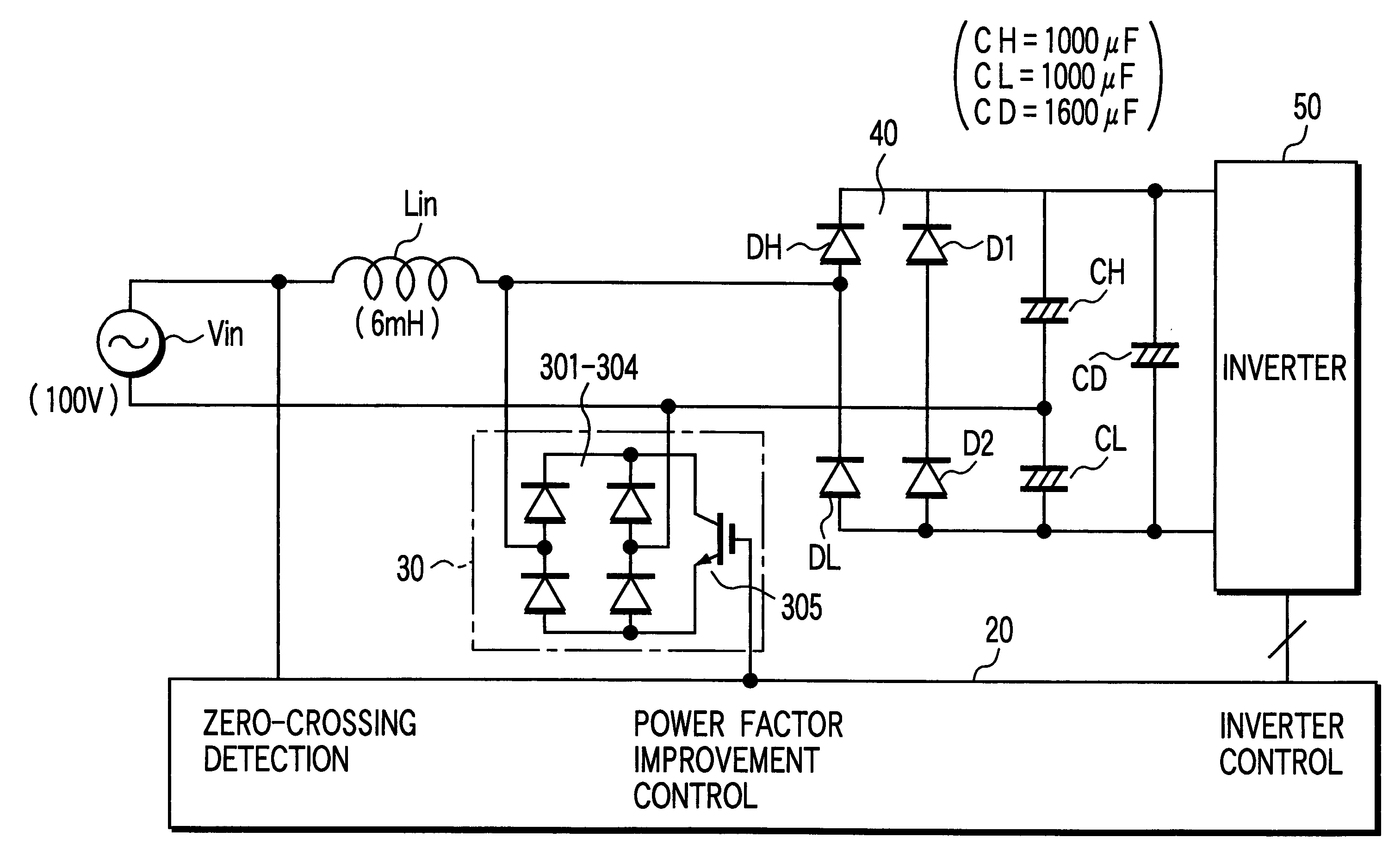
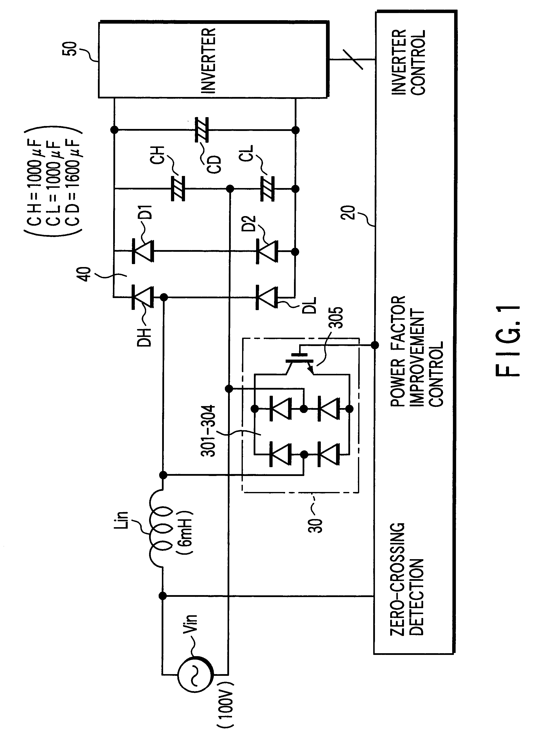
FIG. 1 is a circuit diagram showing the arrangement of a power conversion apparatus according to the present invention.
The same reference numerals as in FIG. 17 showing a conventional apparatus including a conversion section and an inversion section according to the present invention, as described above, denote the same parts in FIG. 1, and a description thereof will be omitted.
In the first embodiment, a booster 30 is connected between the load terminal of a reactor Lin connected to one terminal of an AC power supply Vin, and the other terminal of the AC power supply Vin.
An outdoor controller 20 serving as a control unit including a microcontrol unit (MCU) detects the zero-crossing point of the AC power supply Vin, and controls the booster 30 and an inverter 50.
The booster 30 is made up of four bridge-connected diodes 301 to 304 and one insulated-gate bipolar transistor (IGBT) 305.
The four diodes 301 to 304 constitute a full-wave rectifying circuit. The AC input terminal of the full...
second embodiment
FIG. 4 is a circuit diagram showing the arrangement of a power conversion apparatus according to the present invention.
In the second embodiment, the AC power supply voltage is in 200V class. The same reference numerals as in FIG. 17 showing a conventional apparatus denote the same parts in FIG. 4, and a description thereof will be omitted.
In the second embodiment, similar to the case of the AC power supply voltage in 100V class, a reactor Lin is connected between an AC power supply Vin and the AC terminal of a full-wave rectifying circuit made up of bridge-connecting diodes 301 to 304.
The AC input terminal of a booster 30 is connected to the load terminal of the reactor Lin, and the DC output terminal thereof is connected to an IGBT 305.
An outdoor controller 20 including a microcontrol unit (MCU) detects the zero-crossing point of the AC power supply Vin, and controls the IGBT 305 of the booster 30 and an inverter 50.
The power conversion apparatus shown in FIG. 4 processes a large l...
third embodiment
FIGS. 13A and 13B are a circuit diagram showing the arrangement of a power conversion apparatus according to the present invention, and a waveform chart of a power factor improvement control pulse, respectively.
The same reference numerals as in FIG. 4 denote the same parts in FIG. 13A, and a description thereof will be omitted.
If one reactor as the reactor Lin shown in FIG. 4 is given a predetermined inductance, e.g., an inductance of 14 to 20 mH, the power conversion apparatus of the third embodiment increases in size and weight, and may generate large frequency noise.
Using a reactor having such an inductance makes it relatively difficult to manufacture and handle the power conversion apparatus and reduce noise.
In the third embodiment, as shown in FIG. 13A, first and second reactors Lin1 and Lin2 are series-connected in consideration of these situations.
Each of the first and second reactors Lin1 and Lin2 has an inductance of 7.5 mH, and has substantially the same shape and natural ...
PUM
Abstract
This invention provides a power conversion apparatus capable of improving the power factor of the power supply and making the harmonic component of the power supply match or very closer to the IEC standard, and an air conditioner using the same. The power conversion apparatus includes a conversion section for rectifying and smoothing an AC voltage supplied from an AC power supply and converting the AC voltage into a DC voltage, an inversion section for converting the DC voltage prepared by conversion into an AC voltage and supplying the AC voltage to a load, a reactor series-connected to the power supply side of the conversion section, a booster for forcibly short-circuiting the AC power supply via the reactor, and a controller for setting the short-circuiting conduction time by the booster so as to optimize the power factor of the AC power supply in accordance with any one or a plurality of differences between the voltage of the AC power supply, the inductance of the reactor, the circuit arrangement of the conversion section, and an input power. The air conditioner drives a compressor for forming a refrigeration cycle using the power conversion apparatus.
Description
The present invention relates to a power conversion apparatus and an air conditioner using the same and, more particularly, to a power conversion apparatus for rectifying and smoothing an AC voltage supplied from an AC power supply, converting the AC voltage into a DC voltage, reconverting the DC voltage into an AC voltage, and supplying the obtained AC voltage to a load, and an air conditioner using the same.A large-capacity power conversion apparatus for converting an AC voltage supplied from an AC power supply into a DC voltage, further converting the DC voltage into a pulse-width-modulated (PWM) voltage, and supplying the PWM voltage to a load has conventionally been known.For example, as a power conversion apparatus for 400 W to 5 kW, a passive filter power conversion apparatus is available in which a reactor is connected to an AC power supply line, and an AC voltage obtained via the reactor is rectified by a voltage doubling / rectifying circuit in order to increase the power fa...
Claims
Application Information
Patent Timeline
Application Date:The date an application was filed.
Publication Date:The date a patent or application was officially published.
First Publication Date:The earliest publication date of a patent with the same application number.
Issue Date:Publication date of the patent grant document.
PCT Entry Date:The Entry date of PCT National Phase.
Estimated Expiry Date:The statutory expiry date of a patent right according to the Patent Law, and it is the longest term of protection that the patent right can achieve without the termination of the patent right due to other reasons(Term extension factor has been taken into account ).
Invalid Date:Actual expiry date is based on effective date or publication date of legal transaction data of invalid patent.

