Eureka AIR delivers breakthrough ideas for toughest innovation challenges, trusted by R&D personnel around the world.

Building element

a technology of building elements and components, applied in the direction of girders, walls, joists, etc., can solve the problems of inability to bond with aerated concrete, heavy weight of composite steel in concrete structures, and inability to easily manipula

Inactive Publication Date: 2001-02-06
NDD INT
View PDF10 Cites 11 Cited by
  • Summary
  • Abstract
  • Description
  • Claims
  • Application Information

AI Technical Summary

Benefits of technology

The building panels also have excellent strength in that the outer sheathing provides the tensile strength while the inner core provides compressive strength and due to the continuous nature of the outer sheath, this product thus allows a composite action while not requiring to adhere to each other.
Due to the particular construction and the substantial absence of substantial air gaps, the building panels are expected to have a high fire rating.

Problems solved by technology

However the resulting elements, because of the density of the concrete, have been heavy and not readily manipulable when manufactured in the form of prefabricated panels, columns and the like.
This problem of the weight of composite steel in concrete structures is not solved by using a low density material such as aerated concrete to carry the compressive loads.
This bonding effect is not possible with aerated concrete.
The presence of these air pockets results in a lower steel to concrete bonding area, and far less effective bonding.
There are similar difficulties in obtaining adhesion or bonding between reinforcing steel and other light weight alternatives to conventional concrete.

Method used


Image

  • Building element
  • Building element
  • Building element

Examples


Embodiment Construction

Preferably the first end and the second end are so shaped that the first end of one such building element is adapted to engage with the second end of another such building element.

However, plain ends may be acceptable in some instances.

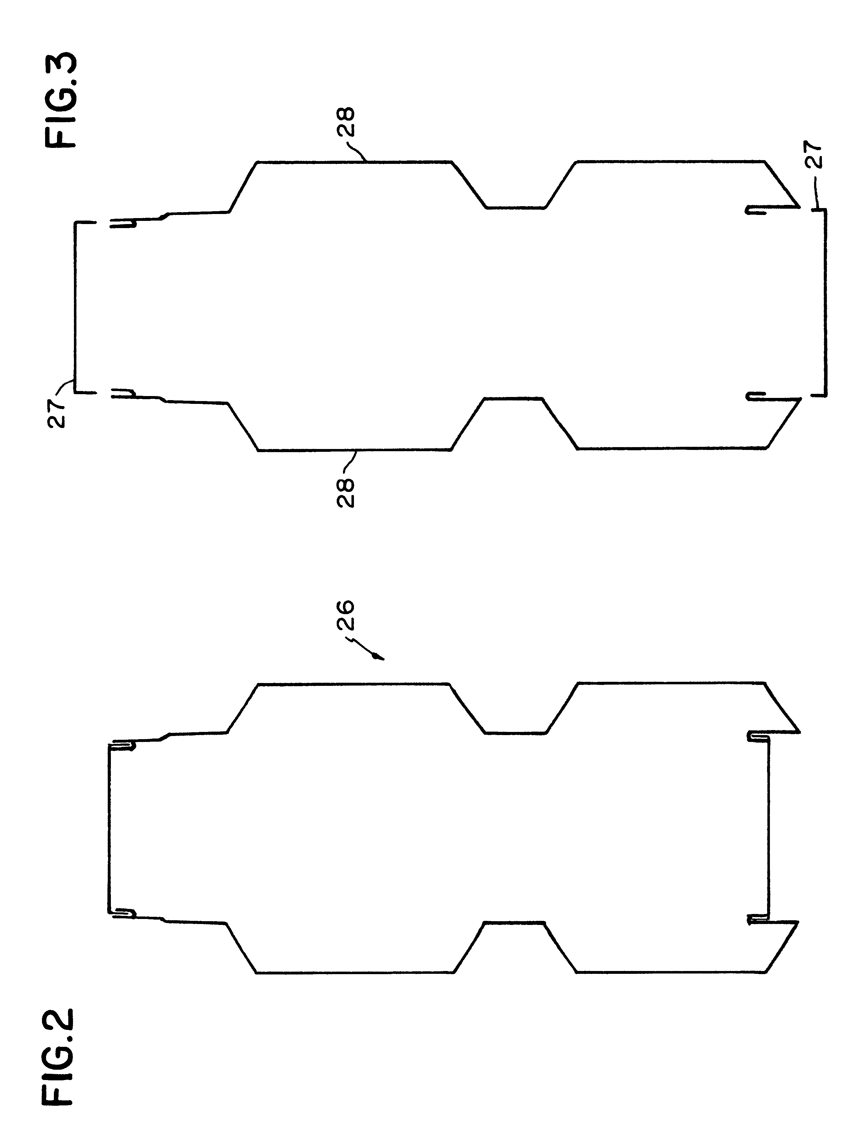
Preferably the sheath comprises at least two components which can interengage with one another to form the sheath. In one instance the sheath comprises four components.

In the last instance, two components define the faces and two components define the edges.

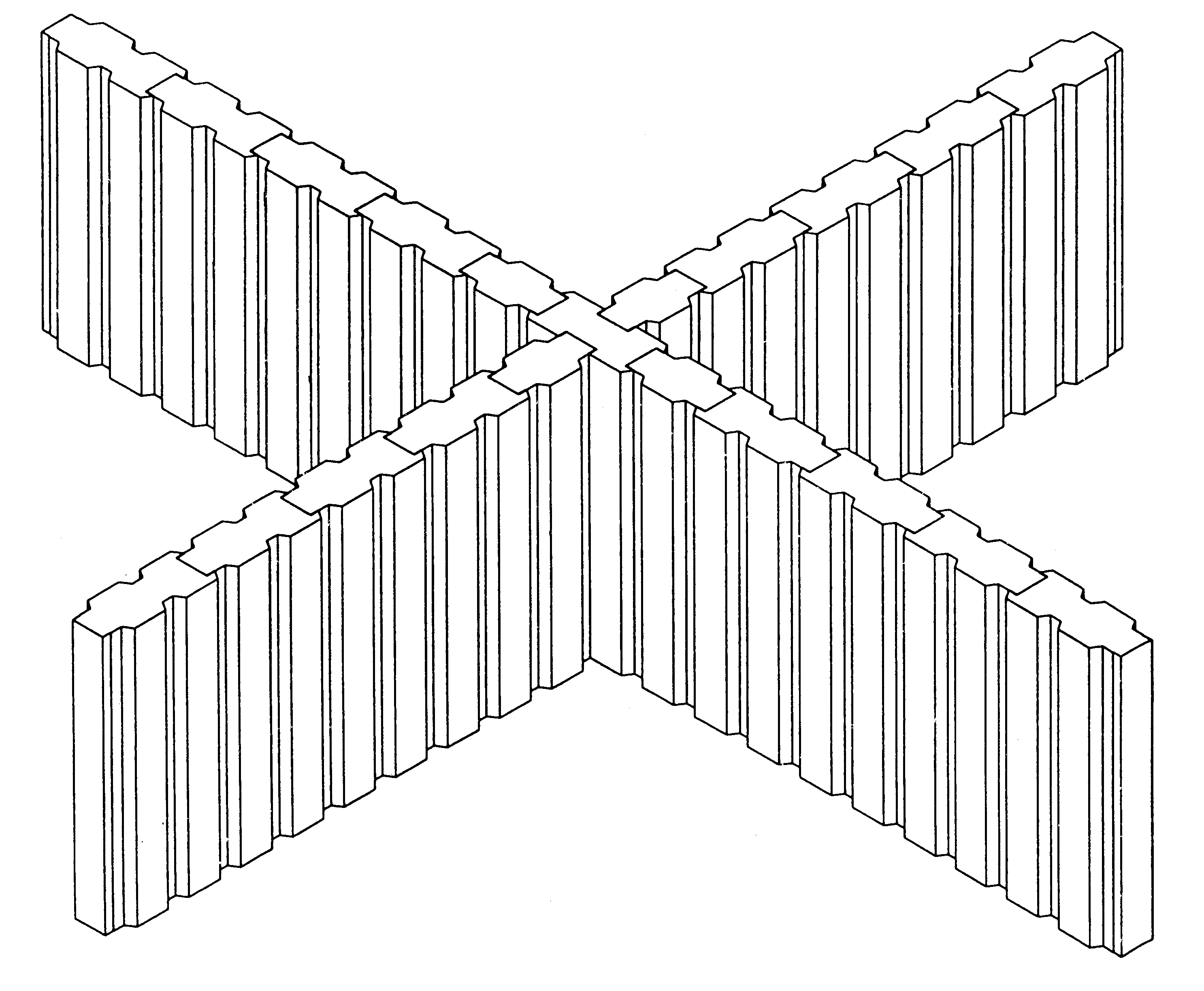
A plurality of such building elements may be assembled edge to edge to form walls, floors, roof, cladding or other parts of a building.

The building elements may extend horizontally, vertically or as desired.

The material of which the sheath is formed need only satisfy the tensile strength requirement.

Suitable materials for the sheath include mild steel, high tensile steel, carbon fibre materials, extruded materials, synthetic plastic-cement fibre composite and asbestos cement or modem replacement th...


PUM


Abstract

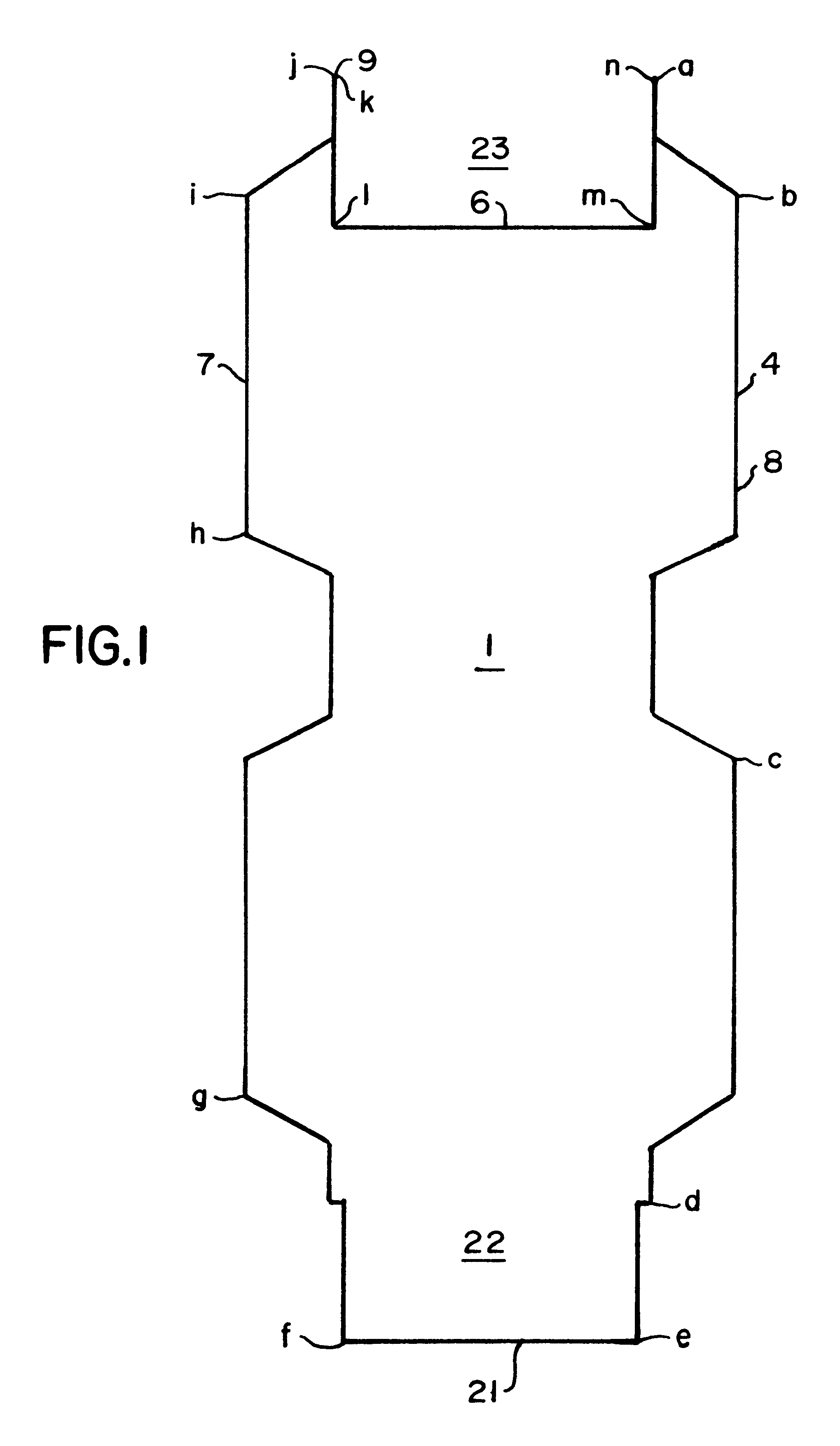
A building element (1) comprising an outer sheath and an inner core, the sheath being formed of a material having a greater tensile strength than compressive strength and the core having a greater compressive strength than tensile strength; wherein the outer sheath is longitudinally extending and has a first face (7) and a second face (8) which are spaced apart, first (9) and second (21) edges and a first and second end; wherein the first face (7) and the second face (8) are joined at the first (9) and second (21) edges to form the outer sheath as a continuous body, and wherein the first edge (9) and the second edge (21) are so shaped that the first edge (9) of one such building element (1) is adapted to locate in the second edge (21) of another such building element (1).

Description

This invention relates to a building element.BACKGROUND TO THE INVENTIONThere is a need for a light weight building element which in its own right has structural integrity and which can be coupled with other such light building elements for the purposes of building panels, walls and various structural components in the formation of buildings.It is an important consideration that such structural elements have significant strength and should have a reasonably high resistance to fire.Classically in order to provide both the compressive strength and the tensile strength required of building elements, steel reinforcement (which has tensile strength) has been provided within concrete (which has compressive strength). However the resulting elements, because of the density of the concrete, have been heavy and not readily manipulable when manufactured in the form of prefabricated panels, columns and the like.This problem of the weight of composite steel in concrete structures is not solved b...

Claims


Application Information

Patent Timeline
Patent Type & Authority Patents(United States)
IPC IPC(8): E04C2/26E04C3/29E04B7/00E04B7/20E04C3/07E04C2/292E04C3/04E04B2/72E04C2/34E04B5/02E04C2/28E04C2/30E04C2/38
CPCE04B7/20E04C2/26E04C2/292E04C3/07E04C3/291E04C2003/0413E04C2003/043
Inventor VISSER, DAVID DIRK
Owner NDD INT
Why Eureka
Eureka Blog
Learn More