Lever lock

a lever lock and lock box technology, applied in the direction of wing knobs, mechanical control devices, keyhole guards, etc., can solve the problem that the required lock box for encapsulating the rod drive requires additional manufacturing and mounting expenditures

Inactive Publication Date: 2001-02-06
EMKA BESCHLAGTAILE GMBH & CO KG
View PDF14 Cites 25 Cited by
  • Summary
  • Abstract
  • Description
  • Claims
  • Application Information

AI Technical Summary

Problems solved by technology

The known configuration of such a retractable lock has the disadvantage that the required lock box for embodying the rod drive requires an additional manufacturing and mounting expenditure.

Method used


Image

  • Lever lock
  • Lever lock
  • Lever lock

Examples


Embodiment Construction

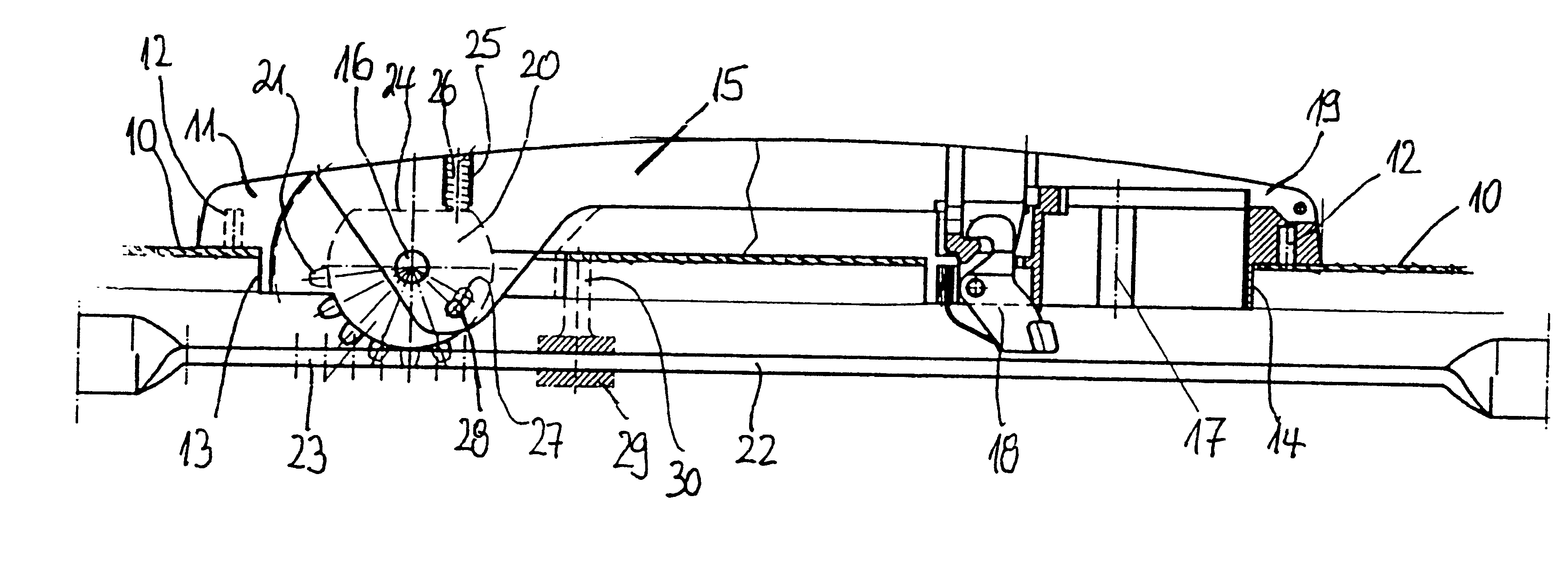
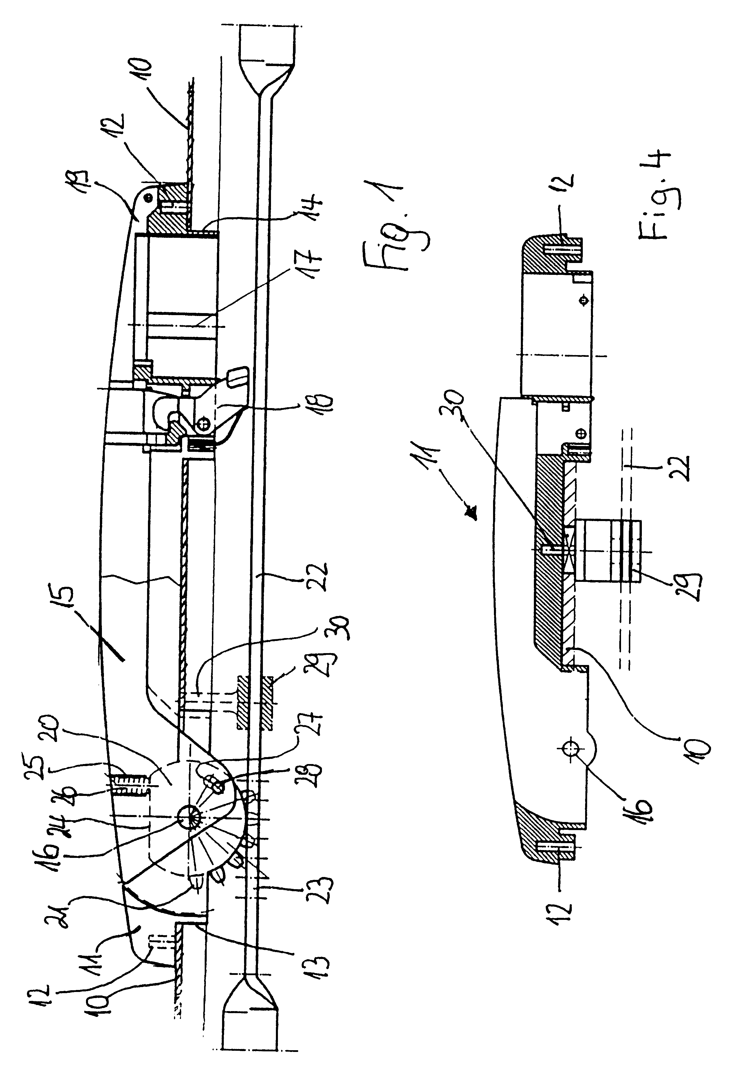
On the exterior side of a door panel 10 a frame 11 is fastened with fastening means 12. The frame 11 penetrates the door panel with an upper projection 13 and a lower projection 14.

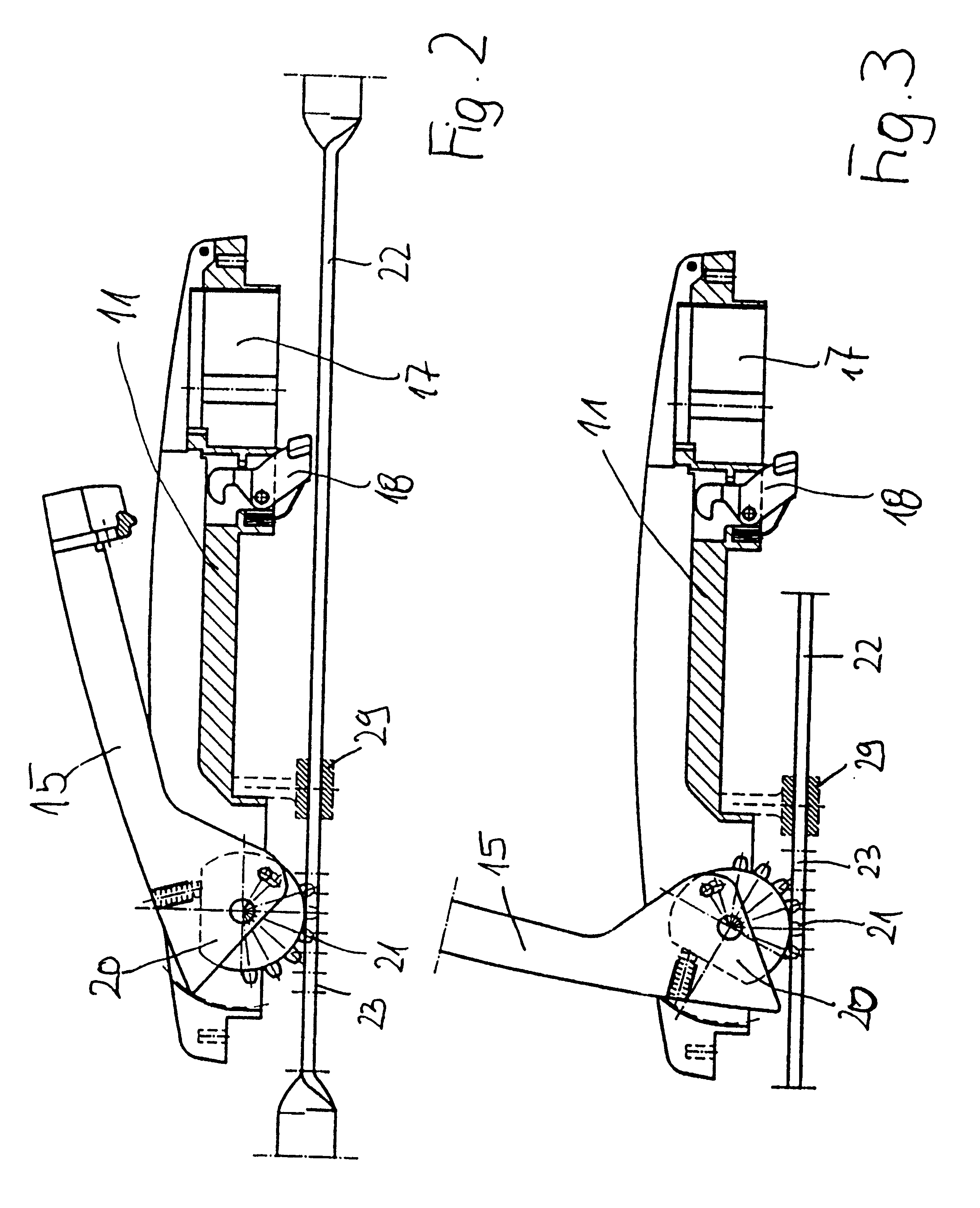
In the area of the upper projection 13 of the frame 11 a lever grip 15 is rotatably supported on a bearing axle 16 within the frame 11 such that a rotary movement of the lever grip 15 is possible in a plane which is perpendicular to the door panel 10.

In the area of the lower projection 14 of the frame 11 a locking device 17 is provided which is not shown in detail in the drawing. It acts on a lock 18 arranged in the frame 11 and acting on the lever grip 15 so that the lever grip 15 in the retracted position can be secured by the locking device 17. The locking device 17 is covered by a sliding cover 19 which is slidably guided on the frame 11 so as to be non-detachable and which is embodied as a U-shaped hollow body. For releasing the locking device 17, the cover is moved in the longitudinal direction of t...


PUM


Abstract

A retractable lock for doors is provided that includes a frame mountable on the front side of the door panel for receiving a retractable lever grip. The lever grip is moveable along a release path between a retracted position inside the frame, where it is secured by a locking device, and an actuating position outside the frame. Further rotation of the lever grip along an actuating path transmits into rotational movement of a pinion which drives a locking rod, which is longitudinally slidably guided at the inner side of the door panel by engagement of outer teeth of the pinion at cutouts of the rod.

Description

BACKGROUND OF THE DESCRIPTIONThe invention relates to a retractable lock for doors, in particular of thin-walled switching cabinets, with a frame mountable on the front side of the door panel and designed for receiving the retractable lever grip, wherein the lever grip in the folded position inside the frame can be secured by a locking device and can be folded along a release path from the retracted position into an actuating position outside of the frame. The further rotation of the lever grip along an actuating path is transmitted into the rotational movement of a pinion which drives a locking rod, which is longitudinally slidably guided at the inner side of the door panel, by engagement of the outer toothing of the pinion at cutouts of the rod.A pivot lever lock with the aforementioned features is disclosed in European Patent Document 0 261 266. In such locking devices coupled to at least one locking rod, a lock box with a pinion arranged in a plane parallel to the door blade is ...

Claims


Application Information

Patent Timeline
Patent Type & Authority Patents(United States)
IPC IPC(8): E05B13/00E05B5/02E05C9/02E05C9/00E05B5/00E05B7/00
CPCE05B1/0092E05B13/002E05C9/021E05C9/006Y10T70/5792Y10T70/5761Y10T292/57E05B7/00
Inventor VON KATHEN, ACHIMSAWATZKI, GERD
Owner EMKA BESCHLAGTAILE GMBH & CO KG
Why Eureka
Try Eureka