Plasma display and method for manufacturing the same

a technology of plasma display and manufacturing method, which is applied in the manufacture of electrode systems, cold cathode manufacturing, electric discharge tube/lamp manufacture, etc., can solve the problems of disturbance, cross-talk, and insufficient preventing swelling of the plasma display and other problems

Inactive Publication Date: 2001-02-06
PANASONIC CORP
View PDF7 Cites 70 Cited by
  • Summary
  • Abstract
  • Description
  • Claims
  • Application Information

AI Technical Summary

Problems solved by technology

In such circumstances, due to differences in the firing shrinkage between the upper and lower regions of the barrier ribs, there has been the problem that the ends of the barrier ribs separate from the substrate and spring up as shown in FIG. 4, or the upper portion of the barrier rib swells upwards without separation as shown in FIG. 5.
As a result of such a gap, there has been the problem that cross-talk occurs at the time of discharge and disturbance is produced in the picture.
However, none of these methods has been adequate in terms of preventing the swelling.
Again, in Japanese Unexamined Patent Publication No. 6-150832, there is described a method in which the barrier rib ends are given a stepped form, but the prevention of swelling is inadequate.

Method used


Image

  • Plasma display and method for manufacturing the same
  • Plasma display and method for manufacturing the same
  • Plasma display and method for manufacturing the same

Examples


example 2

A dielectric layer paste was applied onto a glass substrate in the same way as in Example 1, except that the dielectric layer paste was a photosensitive paste obtained by mixing together glass (2), filler, polymer (2) and monomer (2) at a weight ratio of 22.5:2.2:10:10:0.3:1.6 respectively. The thickness after drying was 15 .mu.m. Instead of carrying out preliminary firing, exposure to ultraviolet rays was carried out from the upper face with an ultrahigh-pressure mercury lamp of output 50 mJ / cm.sup.2, at an exposure level of 1 J / cm.sup.2. Thereafter, a plasma display was produced in the same way as in Example 1. The dielectric layer was fired at the same time as the firing of the barrier rib pattern, Evaluation was conducted in the same way as in Example 1. The results are shown in Table 1.

example 3

The same procedure was carried out as in Example 1 except that, when applying the barrier rib photosensitive paste onto the substrate by screen printing, the printing was carried out at a thickness of 50 .mu.m with a screen printing plate of area greater than the length of the photo-mask barrier rib pattern length, and then printing was carried out at a thickness of 100 .mu.m using a screen printing plate of printing area smaller than the photo-mask barrier rib pattern length in the same way as in Example 1.

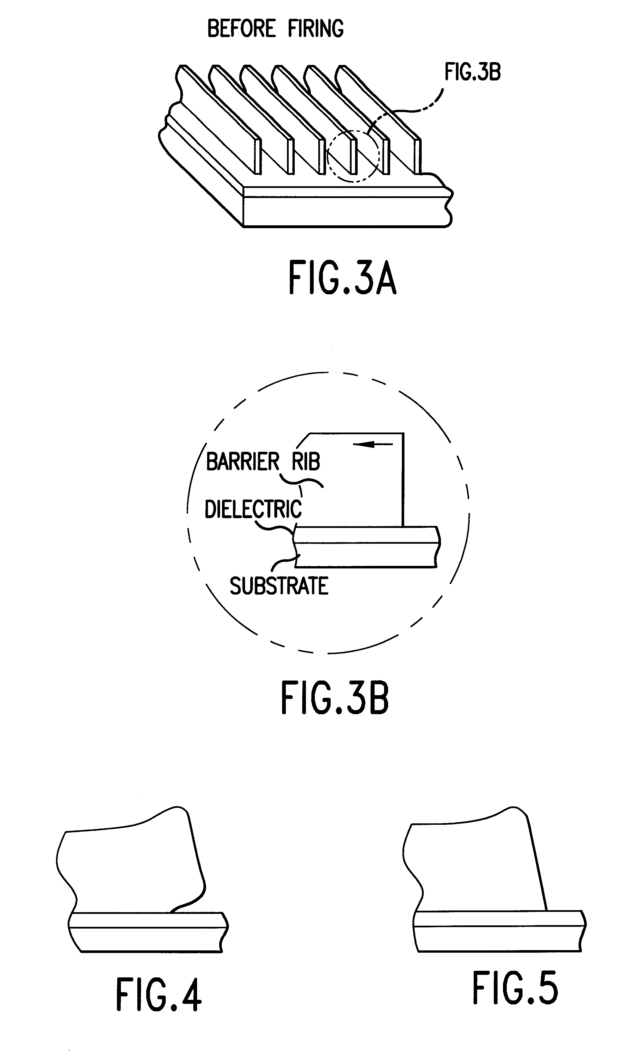
When pattern formation was carried out, the ends of the barrier rib lower layer portion of thickness 50 .mu.m formed a right angle shape, and the ends of the barrier rib upper layer portion of thickness 100 .mu.m were inclined and had the shape shown in FIG. 14.

When firing was carried out in the same way as in Example 1, the ends of the lower layer portion (which had a height of 33 .mu.m after firing) produced a 10 .mu.m swelling but the ends of the upper layer portion (which had...

example 4

The formation of the barrier rib pattern was carried out in the same way as in Example 1 except that when applying the barrier rib paste on the substrate a slit die coater was used, with application being carried out at a thickness prior to drying of 250 .mu.m and, before drying, air was jetted using a nozzle of internal diameter 0.4 mm to form an inclined face at the ends of the applied film. The air pressure was 2.5 kgf.cm.sup.2 and the jetting was at an angle of inclination of 45.degree. from the perpendicular to the substrate. Thereafter, the plasma display was produced and evaluated in the same way as in Example 1. The results are shown in Table 1.


PUM


Abstract

The plasma display of the present invention is a plasma display in which a dielectric layer and stripe-shaped barrier ribs are formed on a substrate, and it is characterized in that there are inclined regions at the lengthwise direction ends of said barrier ribs and, furthermore, the height (Y) of the inclined regions and the length (X) of the base of the inclined regions are within the range 0.5<=X/Y<=100. Moreover, the method of the present invention for manufacturing a plasma display is characterized in that the aforesaid stripe-shaped barrier ribs are formed via a process in which a pattern of stripe-shaped barrier ribs having inclined regions at the ends is formed on a substrate using a barrier rib paste comprising inorganic material and organic component, and a process in which said barrier rib pattern is fired.

Description

The present invention relates to a plasma display and to its method of manufacture. Plasma displays can be used for large size televisions and computer monitors.TECHNICAL BACKGROUNDWhen compared to liquid crystal panels, high speed display is possible with plasma displays (PDPs) and, furthermore, it is easy to produce large sizes, so they are used in fields such as OA equipment and advertising display devices. Moreover, advances into fields such as high quality televisions is greatly expected.Along with such broadening of applications, colour plasma displays with numerous fine display cells are attracting attention. Now, taking an AC type plasma display as an example for explanation, plasma discharge is produced between facing anodes and cathodes within discharge spaces provided between a front glass substrate and a rear glass substrate, and the ultraviolet rays generated from a gas sealed within these discharge spaces strike phosphors provided within the discharge spaces, thereby p...

Claims


Application Information

Patent Timeline
Patent Type & Authority Patents(United States)
IPC IPC(8): H01J9/24H01J17/49H01J11/36
CPCH01J9/242H01J11/12H01J11/36H01J2211/363H01J9/24
Inventor HORIUCHI, KENIGUCHI, YUICHIROMASAKI, TAKAKIMORIYA, GODEGUCHI, YUKICHIARIZUMI, KIWAMEKITAMURA, YOSHIYUKITANI, YOSHINORISAKUMA, ISAMU
Owner PANASONIC CORP
Why Eureka
Try Eureka