Mechanical interlocking means for retaining wall

a technology of mechanical interlocking and retaining walls, which is applied in the direction of mining structures, excavations, artificial islands, etc., can solve the problems of difficult to provide a strong enough connection device to connect the retaining wall, the installation of prior art devices on the retaining wall is often tedious and time-consuming, and the difficulty of attaching the support members to the modular blocks

Inactive Publication Date: 2001-02-13
SCR STI LLC
View PDF15 Cites 93 Cited by
  • Summary
  • Abstract
  • Description
  • Claims
  • Application Information

AI Technical Summary

Problems solved by technology

A major difficulty is encountered in attaching the support members to the modular blocks.
However, installation of these prior art devices onto retaining walls is often tedious and time consuming.
In addition, difficulties are encountered in providing a strong enough connecting device connecting the retaining wall with the support members, in order to support the heavy forces placed on the retaining wall.
However, the mats may slip within the earthen formation, and Hilfiker I does not teach or suggest utilizing any method to prevent slippage of the grid work mats.
Davis I suffers from the disadvantage of a complex and time consuming process of threading the male members into female members in order to connect the wire mesh reinforcement units to the retaining wall.
However, Davis II is a more complex and expensive system than the present invention.

Method used


Image

  • Mechanical interlocking means for retaining wall
  • Mechanical interlocking means for retaining wall
  • Mechanical interlocking means for retaining wall

Examples


Embodiment Construction

An improved method and system for attaching a welded wire gridwork panel to a plurality of face panels of a retaining wall is disclosed.

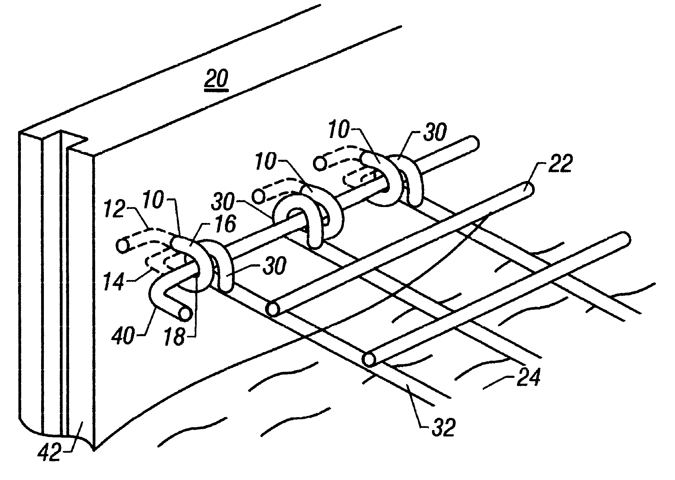
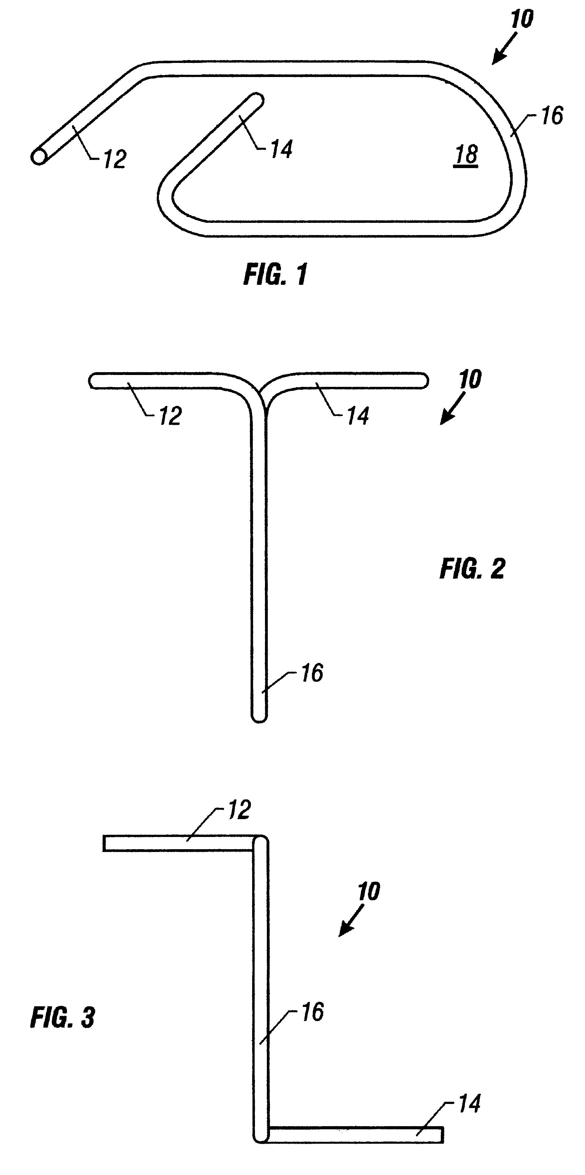
FIG. 1 illustrates a perspective view of a preferred embodiment of an anchor link 10 of the present invention. The anchor link includes two spaced apart L-shaped legs, an upper leg 12 and a lower leg 14. The upper leg and lower leg are joined by a U-shaped projecting end 16. The anchor link forms a vertical loop 18 to which welded wire grid-work panels are attached.

FIG. 2 illustrates a top plan view of the anchor link 10 of FIG. 1.

FIG. 3 illustrates a front elevational view of the anchor link 10 of FIG. 1.

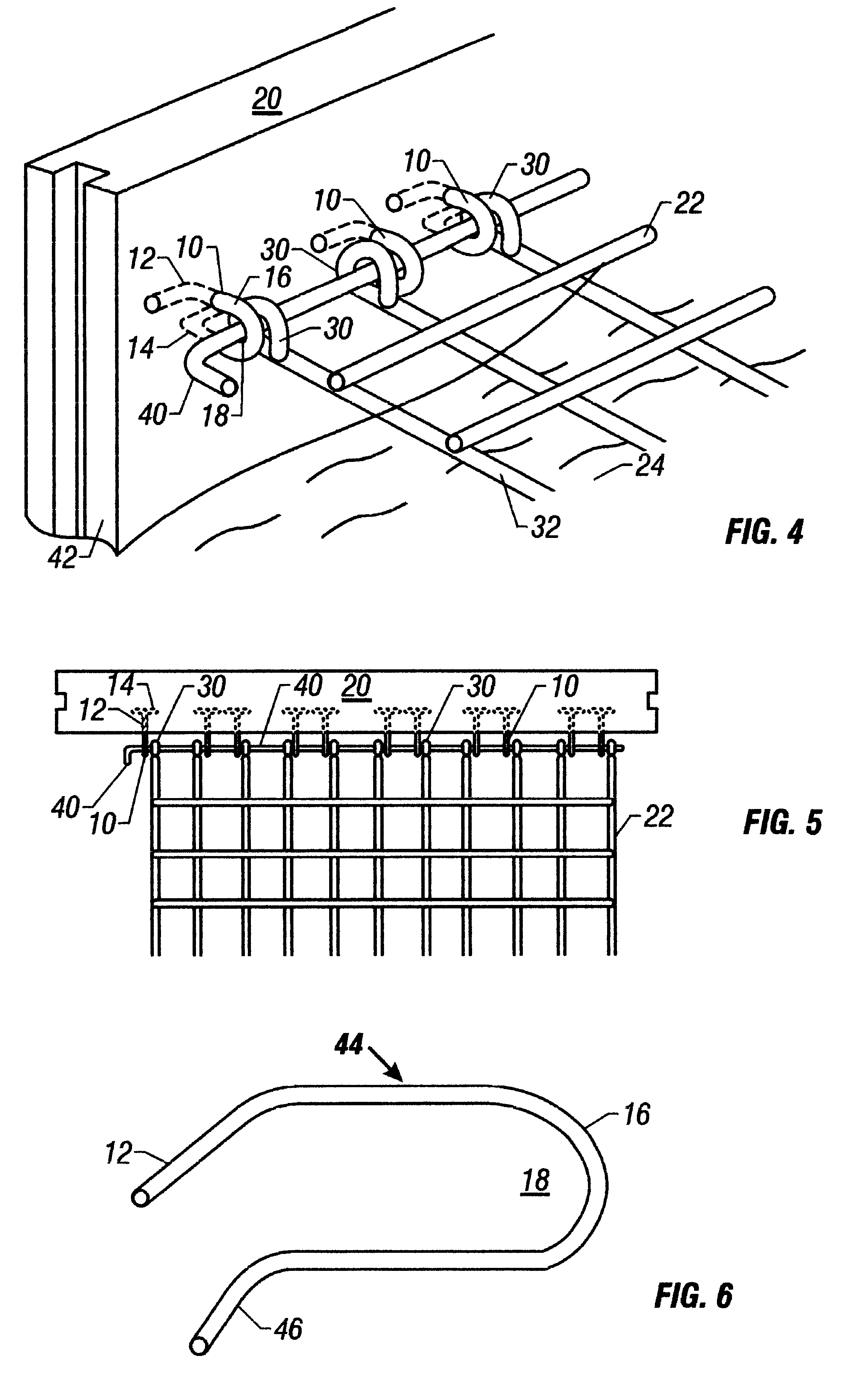
FIG. 4 illustrates a perspective view of a plurality of anchor links 10 fixed within a face panel 20 and connected to a welded wire grid-work panel 22. The grid-work panel extends perpendicularly from the back of the retaining wall into soil 24. A plurality of wire loops 30 are formed at an edge of the grid-work panel, by bending the ends of a plur...


PUM


Abstract

An improved method and system for attaching a welded wire grid-work panel to a plurality of face panels of a retaining wall. The method first begins by providing a plurality of stackable face panels, each face panel having a plurality of anchor links fixed within a back portion of the face panels. Each of the anchor links forms a vertical loop extending outwardly generally perpendicular to the back portion of the face panels. Additionally, each anchor link includes two legs extending laterally from each anchor link within the face panel. Next, a first tier of the face panels is disposed at the bottom of the embankment being erected. Soil is then back-filled behind the first tier of panels to a level of the anchor links disposed within the first tier of face panels. A welded wire grid-work panel, which extends perpendicularly from the back portion of the face panels into a soil embankment, is positioned so that a plurality of wire loops at the edge of the grid-work panel aligns with the vertical loops. A connector rod is extended through the vertical loops of the anchor links and the wire loops of the grid-work panel. Next, additional soil is back-filled behind the first tier of face panels and over the anchor links, vertical loops, wire loops, and grid-work panel to a level at a top edge of the first tier of face panels. The method is repeated until the desired height of the embankment is attained.

Description

1. Technical Field of the InventionThis invention relates to an improved method and system for use with earth retaining structures, and more particularly, an improved retaining wall link and loop combination for attaching a welded wire gridwork panel to the face panels of the wall. This utility patent application claims the priority date of Provisional Patent Application Ser. No. 60 / 077,724 filed Mar. 12, 1998 and is hereby incorporated by reference.2. Description of Related ArtA retaining wall is used for retaining earth and / or other backfill material placed behind the wall. Elongated support structures normally extend from various locations on the back surface of the wall into the backfill material. The support members are embedded into the backfill material and prevent the wall from buckling outwardly.The retaining wall may be constructed of an unbroken stretch of concrete which usually is poured on site. Alternatively, the wall may be constructed of a plurality of modular concre...

Claims


Application Information

Patent Timeline
Patent Type & Authority Patents(United States)
IPC IPC(8): E02D29/02
CPCE02D29/0241
Inventor SHAW, KENNETH L.
Owner SCR STI LLC
Why Eureka
Try Eureka