Thin ice inflatable rescue ladder

a rescue victim and inflatable technology, applied in life-saving, waterborne vessels, vessel safety, etc., can solve the problems of increasing the jeopardy and discomfort of such victims, taking too much time, and affecting the rescue of victims,

Inactive Publication Date: 2001-02-20
SENGER DAVID
View PDF13 Cites 25 Cited by
  • Summary
  • Abstract
  • Description
  • Claims
  • Application Information

AI Technical Summary

Benefits of technology

to indicate a device of the type disclosed above which avoids the disadvantages inherent in the state of the art. In particular, the device i

Problems solved by technology

In the related art, it is known that boat rescues of persons or animals in distress can take too much time over a body of water and be even slower over thin ice, increasing the jeopardy and disco

Method used


Image

  • Thin ice inflatable rescue ladder
  • Thin ice inflatable rescue ladder
  • Thin ice inflatable rescue ladder

Examples


Embodiment Construction

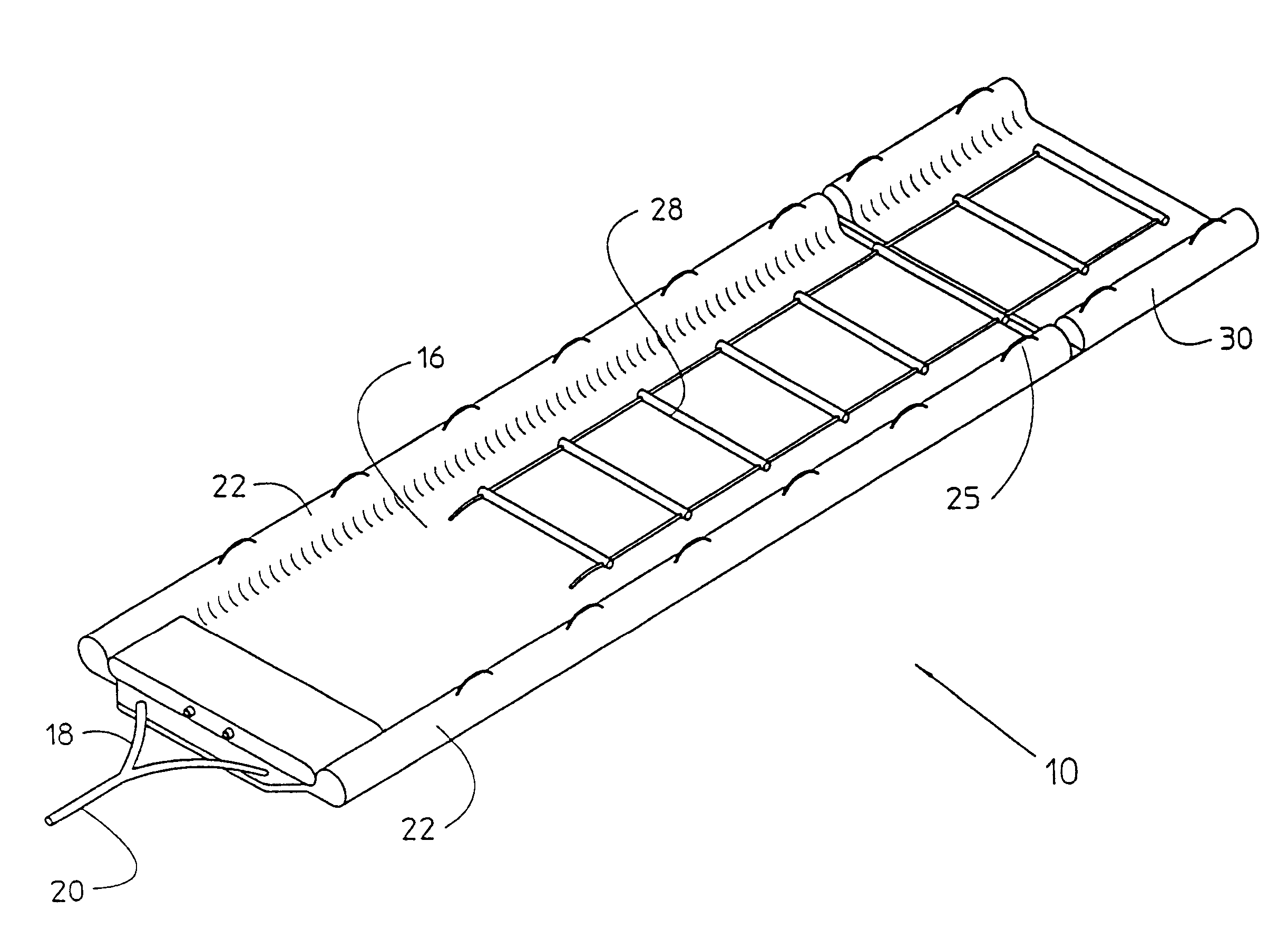
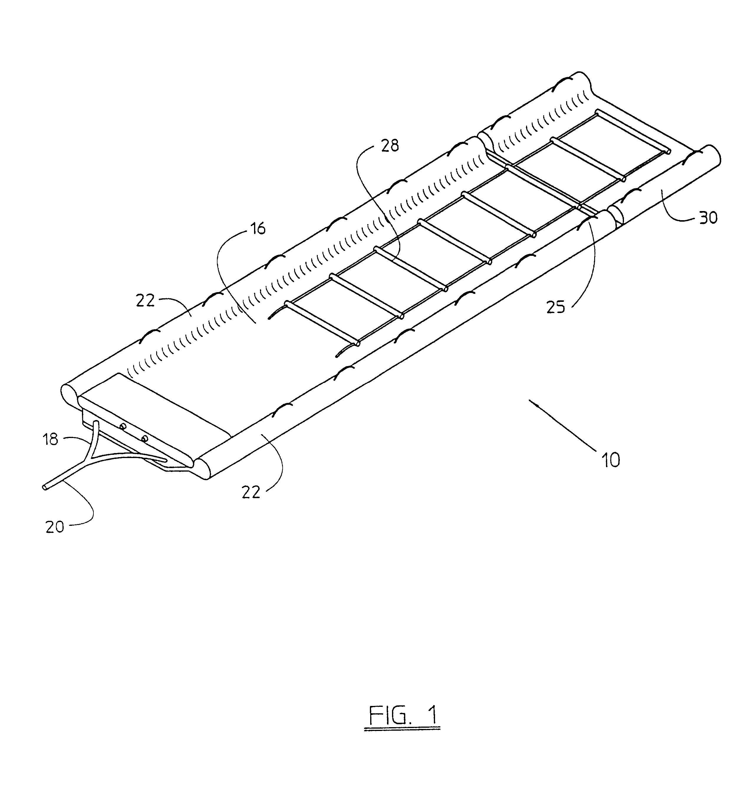
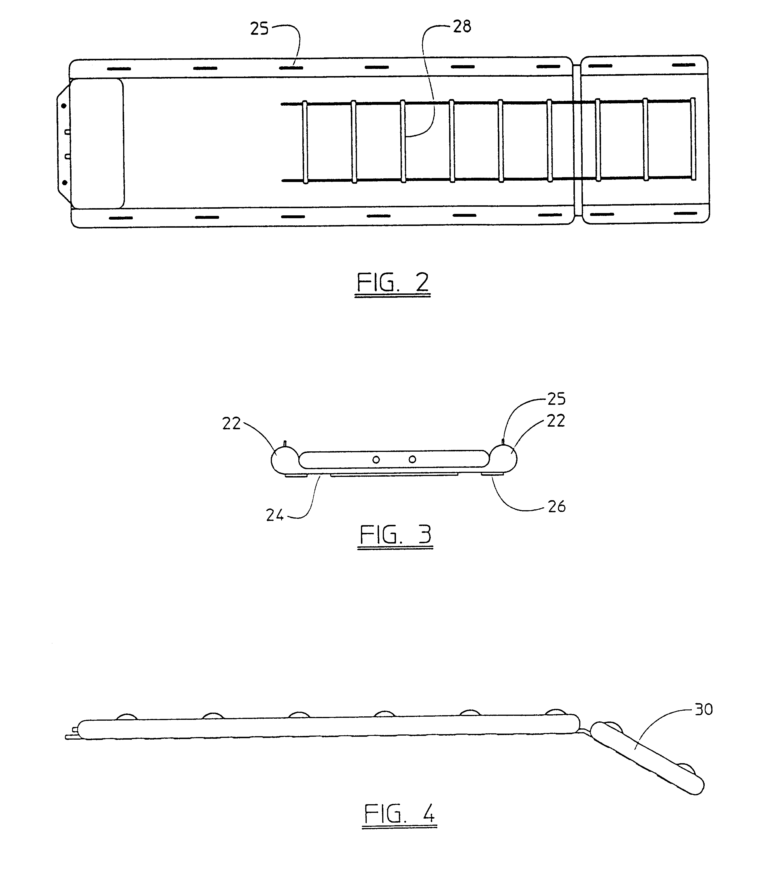
of the Figures Referring now to FIGS. 1-4, a thin ice inflatable rescue ladder 10 is shown, according to the present invention, forming a hinged ramp 16 and further pointed and then secured by anchor lines 18 and 20 to the shore. The ramp 16 is inflatable, and is provided having a pair of spaced inflatable tubes 22, a flexible floor 24 there-between, defining a passageway between said tubes. Linearly aligned along the uppermost ridge of each tube 22 are a series of individual gripping elements 25, shown herein individually as a rope-type loop. On the under surface of the floor 24 is a gripping surface 26 that allows the ramp 16 to assist in maintaining position when deployed upon ice. Within the passageway is mounted a rope ladder element 28 that lies flat against the flexible web. It is anticipated that the ladder element 28 would be mounted only along the lowermost two thirds of the ramp for provided the combined features of providing a gripping and climbing surface for the rescue...


PUM


Abstract

A rescue ramp is provided having a dual lobed, hinged inflatable ramp having two pairs of spaced inflatable tubes and a flexible floor mounted between each and connecting the tubes. A rope ladder is mounted to the floors of the lobes.

Description

1. Field of the InventionThis invention relates to a rescue device, particularly to an inflatable rescue ramp for use on thin ice or similar unfirm surfaces.2. Description of the Related ArtIn the related art, it is known that boat rescues of persons or animals in distress can take too much time over a body of water and be even slower over thin ice, increasing the jeopardy and discomfort of such a victim, when, due to problems such as hypothermia, seconds count.A search of the prior art did not disclose any patents that read directly on the claims of the instant invention; however, U.S. Pat. No. 4,990,114, issued in the name of LeBlanc, Jr. provides an inflatable rescue ramp that forms a lowermost bow element. However, such bow provides and impediment to ingress, making such a ramp difficult for the rescue victim to ascend.There is, therefore, a need and market for a rescue ramp that is hinged, allowing the lowermost portion to descend into the water toward the rescue victim, as wel...

Claims


Application Information

Patent Timeline
IPC IPC(8): B63C9/32B63C9/00
CPCB63C9/32
Inventor SENGER, DAVID
Owner SENGER DAVID
Why Eureka
Try Eureka