Variable output rotary power generator

a rotary power generator and variable output technology, applied in the direction of electric generator control, mechanical energy handling, borehole/well accessories, etc., can solve the problems of affecting the operation of the '071 apparatus, requiring electronic devices to rectify and smooth the electrical output, and affecting the operation of the by-pass valve. , to achieve the effect of maintenance, and reducing the cost of operation

Inactive Publication Date: 2001-02-20
HALLIBURTON ENERGY SERVICES INC
View PDF13 Cites 65 Cited by
  • Summary
  • Abstract
  • Description
  • Claims
  • Application Information

AI Technical Summary

Problems solved by technology

Additionally, for a generator driven by a rotating shaft from a conventional mud-powered turbine, the rotational speed of the input shaft ("input RPM") often varies over a wide range, which, for a conventional permanent magnet generator, presents significant difficulties with respect to the dissipation of excess energy because such dissipation must occur in a downhole environment that typically involves elevated ambient temperatures.
However, the method of the '877 patent is directed to low-power generation rather than high-power generation.
Another drawback of the method of the '877 patent is that it requires electronic devices to rectify and smooth the electrical output, which is initially in the form of relatively high-voltage pulses.
Additionally, the by-pass valve of the '071 apparatus would suffer from the destructive effects of erosion that are frequently encountered in the use of typical drilling fluids (muds).
Again, however, the '738 and '225 machines are not directed to meeting the aforementioned variable electrical requirements.

Method used


Image

  • Variable output rotary power generator
  • Variable output rotary power generator
  • Variable output rotary power generator

Examples


Embodiment Construction

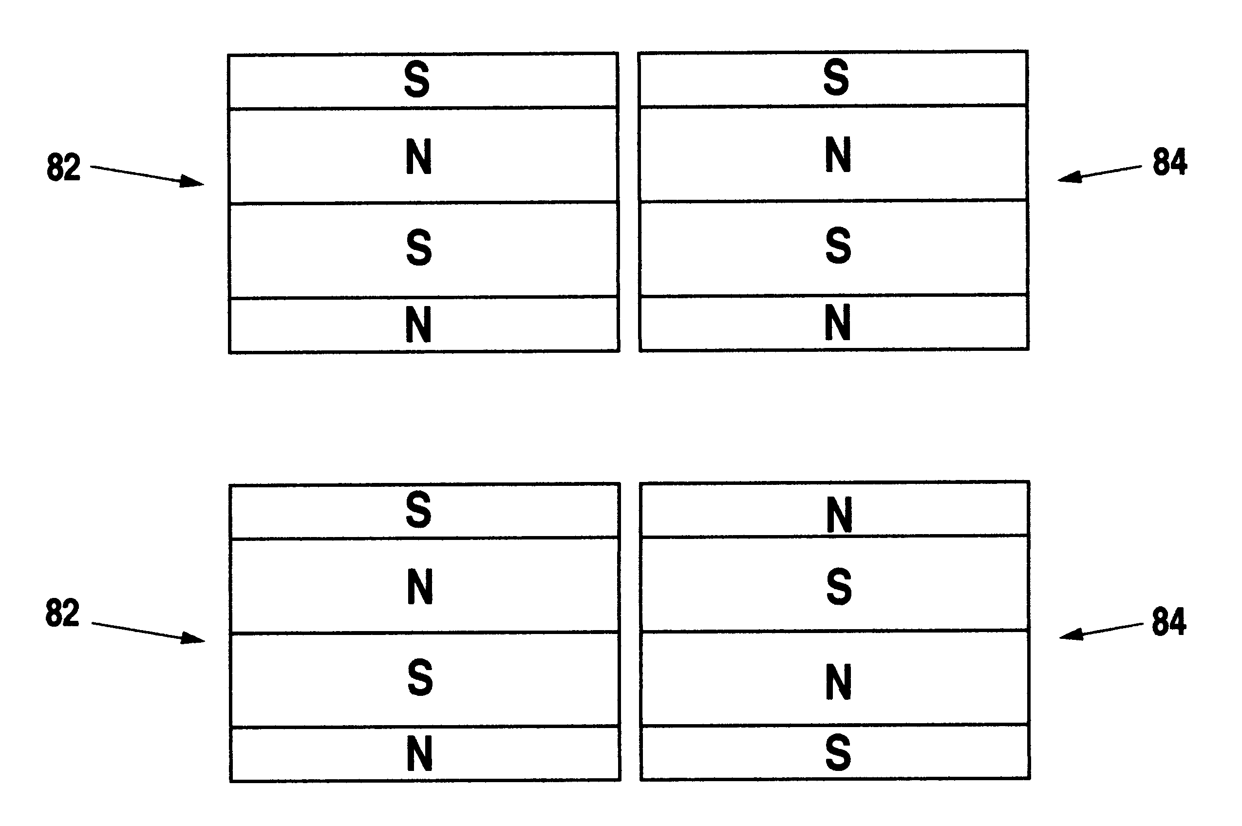
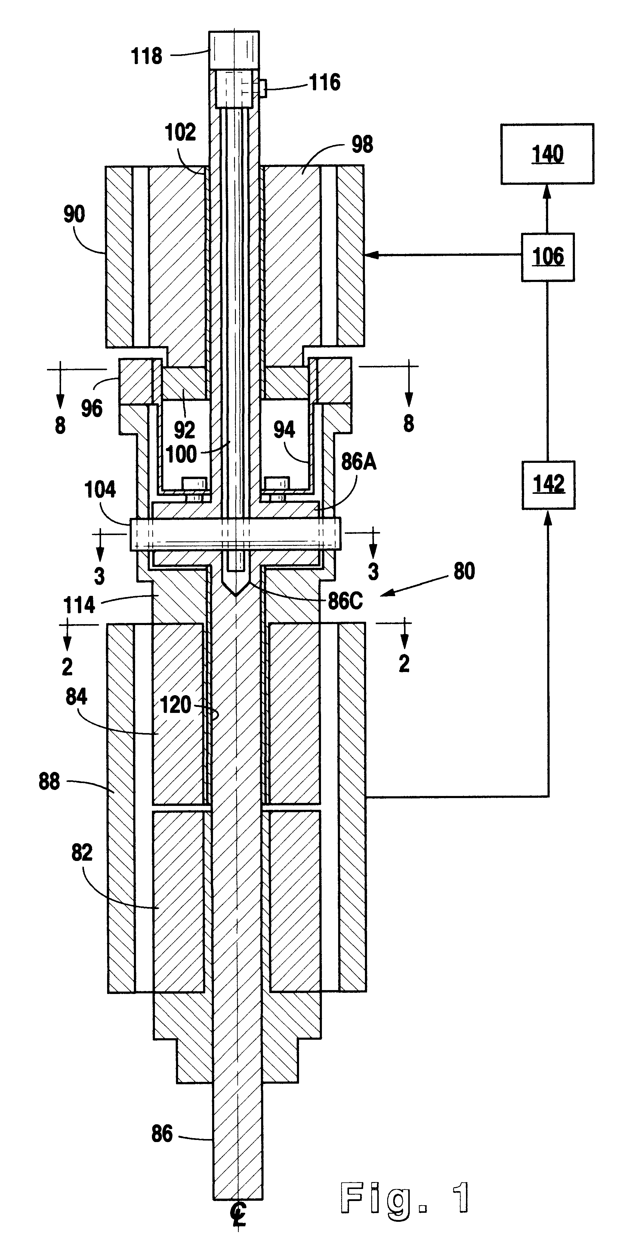
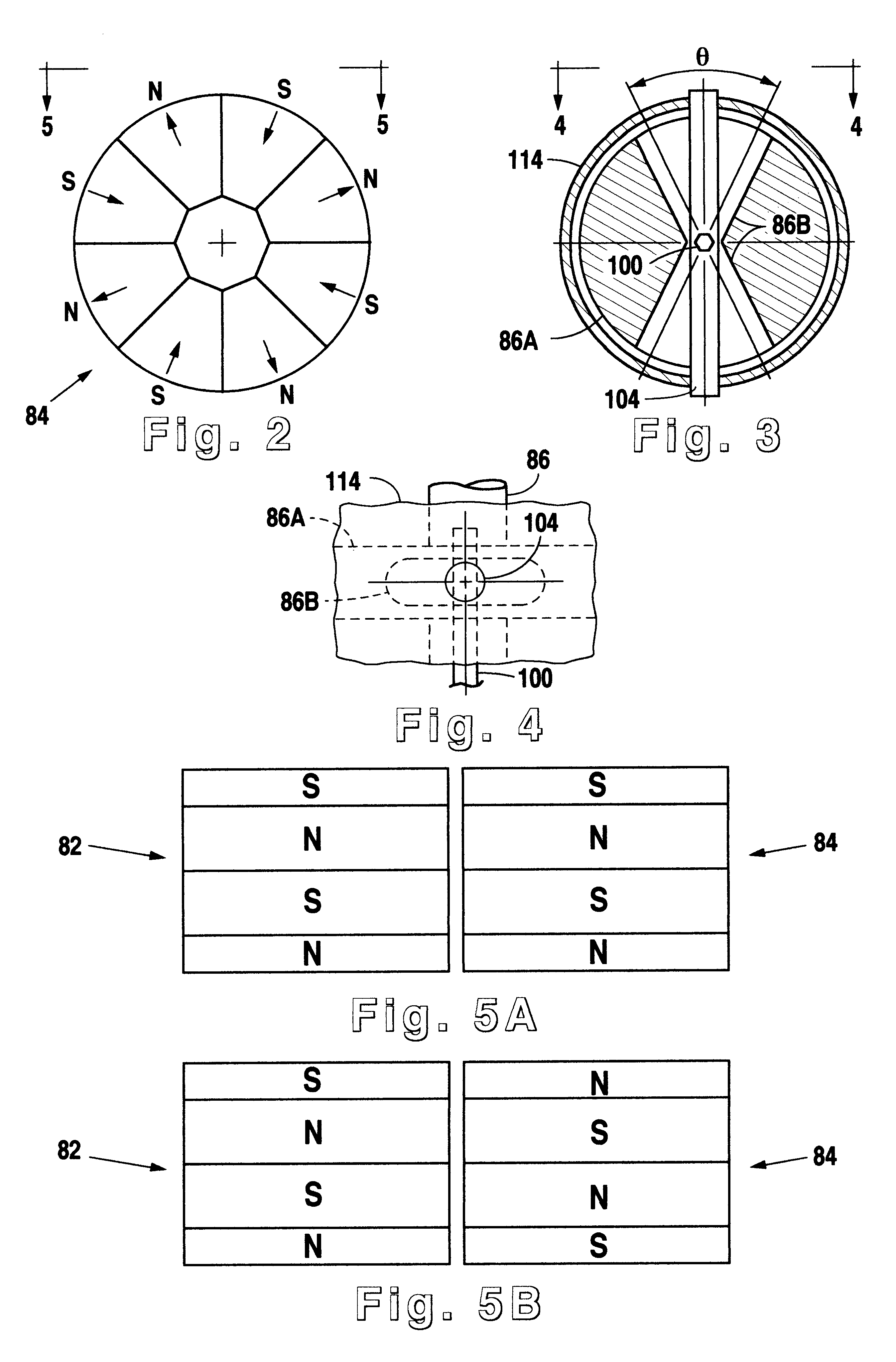
FIG. 1 illustrates an electric generator 80 in accordance with the present invention for supplying electrical energy to a downhole system 140. Electric generator 80 is driven by a drive shaft 86 that is preferably connected to a conventional mud-powered turbine (not shown) and supported by bearings (not shown). Electric generator 80 comprises permanent magnets 82 and 84, which are preferably of equal length and magnetic strength and which rotate inside a fixed main armature 88 to generate downhole electric energy. Because such electric energy is needed over a wide range of rotation speeds of drive shaft 86 (i.e., the mud-powered turbine) and electrical demands of system 140, the electrical output must be controlled. The present invention controls the electrical output by providing a regulator for varying the relative rotational position of movable magnet 84 with respect to fixed magnet 82. Specifically, fixed magnet 82 is fixedly attached to drive shaft 86, but movable magnet 84 is ...


PUM


Abstract

The present invention is directed to a downhole apparatus for quickly generating and regulating variable output electric power by varying the alignment of a pair of axially adjacent permanent magnets rotating within an armature having electrically conductive windings. Each of the permanent magnets comprises a plurality of permanent magnetic segments having circumferentially alternating magnetizations. One of the permanent magnets is fixed to the drive shaft, and the other permanent magnet is movably mounted on the drive shaft to enable the alignment or misalignment, as desired, of the magnetizations of the respective magnetic segments on the pair of permanent magnets. When the magnetizations are completely aligned, the maximum electrical power is generated in the windings of the main armature; conversely, when the magnetizations are completely misaligned, zero electrical power is generated. Thus, the output power is regulated by varying the alignment of the pair of permanent magnets, which is accomplished with a drag torque generator which creates a drag torque that is transmitted to the movable permanent magnet by a torque converter.

Description

1. Field of the InventionThis invention relates generally to an apparatus for generating electric power downhole within an earth borehole. More specifically, this invention relates to a downhole apparatus for generating variable electric output by varying the alignment of permanent magnets rotating within an armature having electrically conductive windings.2. Description of the Related ArtIn the field of petroleum well drilling and logging, recent advancements in drilling and logging technology have produced tools that require increasingly higher levels of electric energy downhole. Moreover, for many modern drilling and logging systems, the electric energy requirements vary over a wide dynamic range of system operating conditions. Thus, during certain operating conditions, such systems require reduced electric energy, and the dissipation of any excess electric energy must not result in destructive effects within the generator and / or the associated regulating electronics. Additionall...

Claims


Application Information

Patent Timeline
Patent Type & Authority Patents(United States)
IPC IPC(8): E21B41/00H02K16/00H02K16/02H02K21/00H02P9/00H02P9/40H02K7/18
CPCE21B41/0085H02K21/029H02P9/40
Inventor BARTEL, ROGER P.
Owner HALLIBURTON ENERGY SERVICES INC
Why Eureka
Try Eureka