Pseudo-3D stereoscopic images and output device

a stereoscopic image and output device technology, applied in the field of pseudo3d stereoscopic images and output devices, can solve the problems of complex preparation, inability to achieve high-fidelity images, and general choice of images

Inactive Publication Date: 2001-02-27
GOOGLE LLC
View PDF3 Cites 88 Cited by
  • Summary
  • Abstract
  • Description
  • Claims
  • Application Information

AI Technical Summary

Problems solved by technology

However, previous systems have required complex preparation and high fidelity images have generally not been possible.
Further, the general choice of images has been limited with the images normally only being specially prepared images.

Method used


Image

  • Pseudo-3D stereoscopic images and output device
  • Pseudo-3D stereoscopic images and output device
  • Pseudo-3D stereoscopic images and output device

Examples


Embodiment Construction

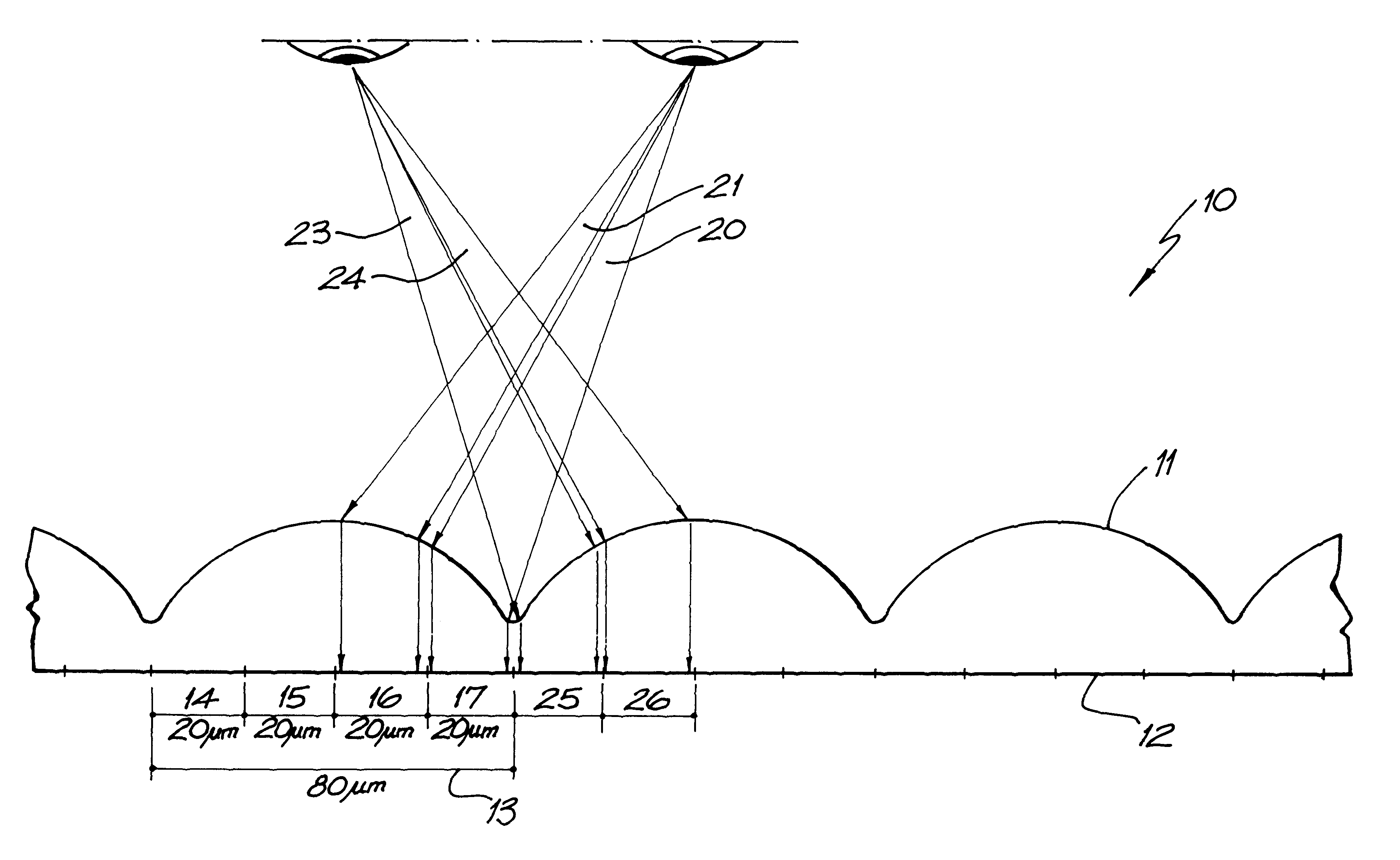
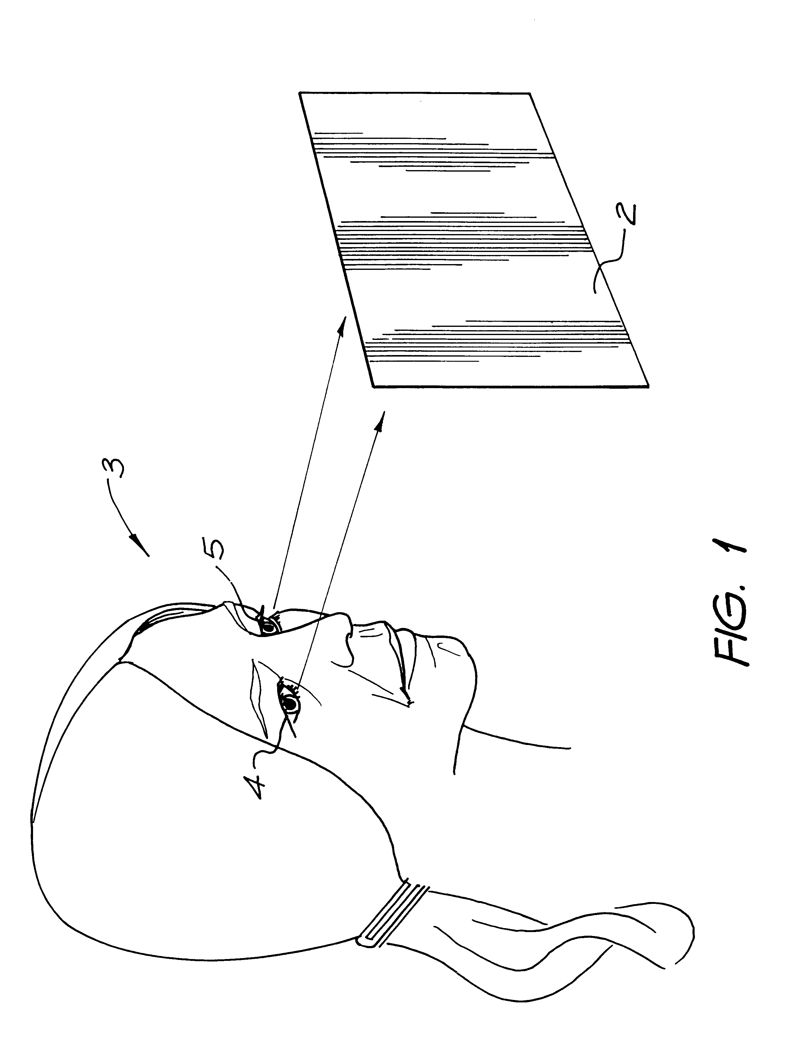
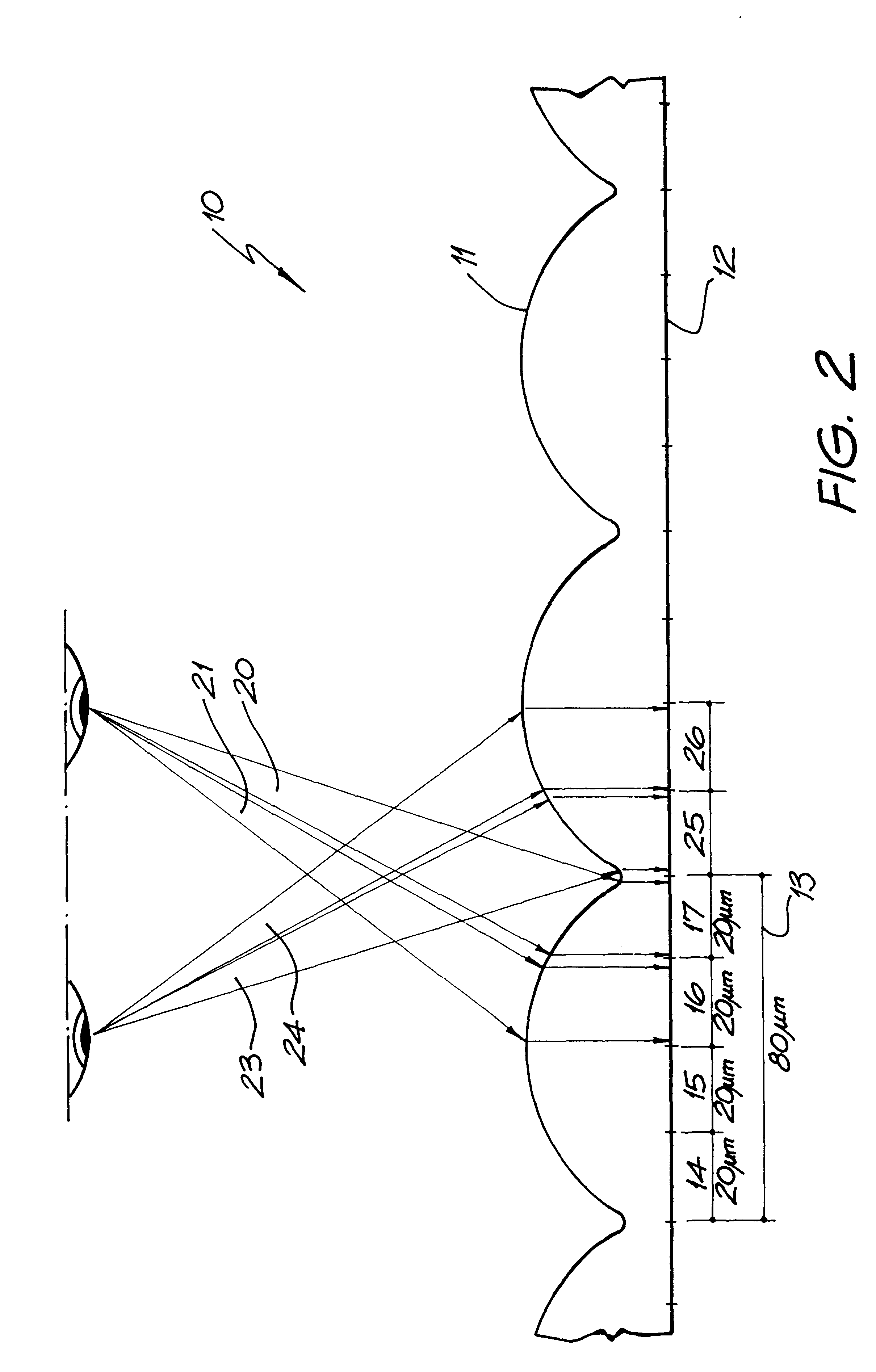
Referring now to FIG. 1, in the preferred embodiment, it is desired to create a photographic image to which allows a viewer 3 to view stereoscopical or pseudo three-dimensional type effects. These effects can be viewed by simultaneously recording two images close together and presenting one image to the viewer's right eye 4 and a second image to the viewer's left eye 5. By recording the image for the left and right eye and then presenting a surface which allows the left eye to view the left stereoscopic image and the right eye to view the right stereoscopic image, a 3-D stereoscopic effect will be produced.

In the preferred embodiment, the photo or stereoscopic image 2 can be constructed, as will become more apparent hereinafter, by means of a series of lenticular transparent columns which image the left and right eye images.

Turning now to FIG. 2, there is illustrated a cross-sectional view of part of the surface of the photographic paper 2. As is illustrated in cross-sectional view ...


PUM


Abstract

A transparent print media comprising a first surface having a polarity of lenticular portions adapted to image left and right stereo images printed on an opposing surface to the first surface so as to produce a stereo photographic image when viewed from the first surface.

Description

The present invention relates to the creation of pseudo-3D stereoscopic images and, in particular, also discloses a camera and printing output device that can create these images on demand.DESCRIPTION OF BACKGROUND ARTThe creation of stereoscopic views, with a first image being presented to the left eye and second image being presented to the right eye, thereby creating an illusion of a three dimensional surface is well known. However, previous systems have required complex preparation and high fidelity images have generally not been possible. Further, the general choice of images has been limited with the images normally only being specially prepared images.There is a general need for being able to produce high fidelity stereoscopic images on demand and in particular for producing images by means of a portable camera device wherein the stereoscopic image can be taken at will.It is an object of the present invention to provide a media for automatic production of stereographic images...

Claims


Application Information

Patent Timeline
Patent Type & Authority Patents(United States)
IPC IPC(8): B41J11/70B41J2/14B41J15/04B42D15/10B41J2/16B41J3/42B41J11/00G06F1/16G06F21/00G07F7/12G07F7/08G06K1/00G06K1/12G06K19/073G11C11/56G06K7/14G06K19/06H04N1/32H04N5/262H04N5/225H04N1/21B41J2/165B41J2/175H04N1/00B41J3/44H04N13/00
CPCB41J3/445B41J11/0005B41J11/70B41J15/04B82Y30/00G06F21/79G06F21/86G06K1/121G06K7/14G06K7/1417G06K19/06037G11C11/56H04N5/225H04N5/2628B41J2/16585B41J2/17596G06F2221/2129H04N23/00G03B27/00H04N23/40
Inventor SILVERBROOK, KIA
Owner GOOGLE LLC
Why Eureka
Try Eureka