Overvoltage sensing and correction circuitry and method for low dropout voltage regulator

a voltage regulator and overvoltage sensing technology, applied in the direction of electric variable regulation, process and machine control, instruments, etc., can solve the problems of low output voltage, low output voltage, and high probability of overshoot in response of error amplifier a1, so as to reduce the severity of output overvoltage conditions

Inactive Publication Date: 2001-03-13
BURR-BROWN CORPORATION
View PDF17 Cites 214 Cited by
  • Summary
  • Abstract
  • Description
  • Claims
  • Application Information

AI Technical Summary

Benefits of technology

The invention aims to improve the LDO voltage regulator to reduce the likelihood of output overvoltage caused by sudden changes in load current.

Problems solved by technology

The technical problem of this patent text is to provide a more efficient and cost-effective method for producing a specific type of chemical compound.

Method used


Image

  • Overvoltage sensing and correction circuitry and method for low dropout voltage regulator
  • Overvoltage sensing and correction circuitry and method for low dropout voltage regulator
  • Overvoltage sensing and correction circuitry and method for low dropout voltage regulator

Examples


Embodiment Construction

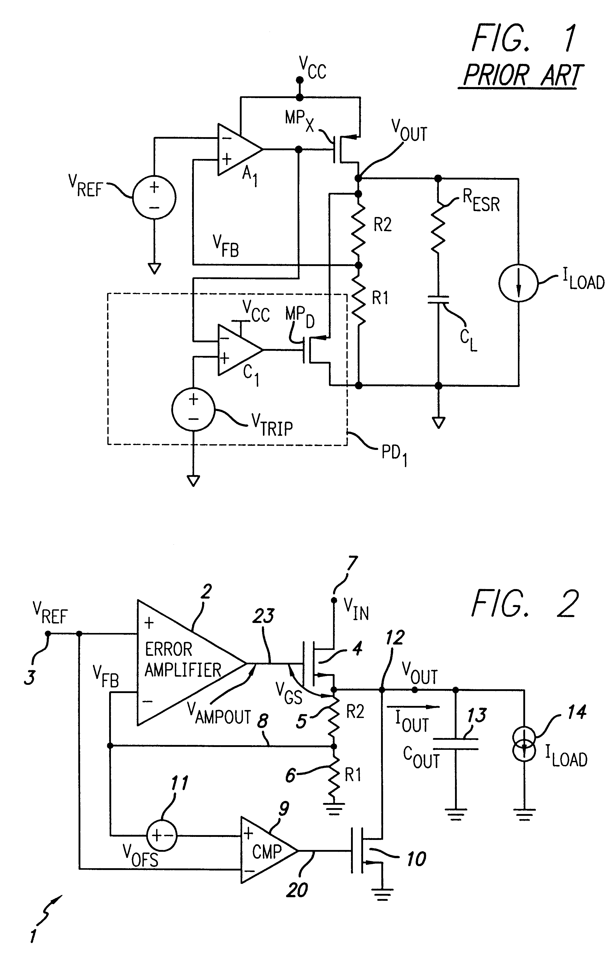
Referring to FIG. 2, LDO voltage regulator 1 includes N-channel output transistor 4 having its drain connected to an unregulated input supply voltage V.sub.IN on conductor 7. The source of transistor 4 is connected to conductor 12, on which a regulated output voltage V.sub.OUT is produced. A large capacitor 13 representing an output capacitance C.sub.OUT is connected between conductor 12 and ground. A variable load 14 that draws a variable load current I.sub.LOAD from output conductor 12 is connected between output conductor 12 and ground. Resistors 5 and 6 are connected in series between output conductor 12 and ground, and the form a voltage divider which produces a feedback signal V.sub.FB on conductor 8. V.sub.FB is applied to the (-) input of an error amplifier 2 having its (+) input connected by conductor 3 to receive a reference voltage V.sub.REF. The output of error amplifier 2 is connected by conductor 23 to the gate of output transistor 4.

In accordance with the present inve...


PUM


Abstract

An LDO voltage regulator includes an error amplifier having a first input coupled to a first reference voltage, a second input receiving a feedback signal, and an output producing a first control signal. An output transistor has a gate, a drain coupled to an unregulated input voltage, and a source coupled to produce a regulated output voltage on an output conductor. A feedback circuit is coupled between the output conductor and a second reference voltage. An overvoltage comparator has a first input coupled to receive the first reference voltage and a second input coupled to respond to the feedback signal to produce a discharge control signal indicating occurrence of an output overvoltage of at least a predetermined magnitude to control a discharge transistor coupled between the output conductor and the second reference voltage. An output current sensing circuit produces a control current representative of the drain current of the output transistor. An offset capacitor is coupled between the output of the error amplifier and the gate of the output transistor, and a servo amplifier has a first input coupled to receive a third reference voltage, a second input coupled to the output of the error amplifier, and an output coupled to the gate of the output transistor to produce a second control signal thereon. A current sensor circuit, a current capacitor, and an AND circuit operate to allow the discharge transistor to be turned on only if the output current is below a certain level.

Description


Claims


Application Information

Patent Timeline
Owner BURR-BROWN CORPORATION
Why Eureka
Try Eureka