Tuned transducer, and methods and systems for tuning a transducer

Inactive Publication Date: 2001-03-20
XEROX CORP
View PDF12 Cites 14 Cited by
  • Summary
  • Abstract
  • Description
  • Claims
  • Application Information

AI Technical Summary

Benefits of technology

Since a transducer can thus be tuned according to this invention, substantial cost savings can be realized because virtually every transducer that is manufactured can be adjusted to operate within specified performance standards, resulting in very good yield.

Problems solved by technology

However, there is a tendency for the response of the segmented waveguide segments to be elevated at one edge and / or to fall off along the opposite edge of the transducer as a result of the continuous mechanical behavior of the resonator device.

Method used


Image

  • Tuned transducer, and methods and systems for tuning a transducer
  • Tuned transducer, and methods and systems for tuning a transducer
  • Tuned transducer, and methods and systems for tuning a transducer

Examples


Embodiment Construction

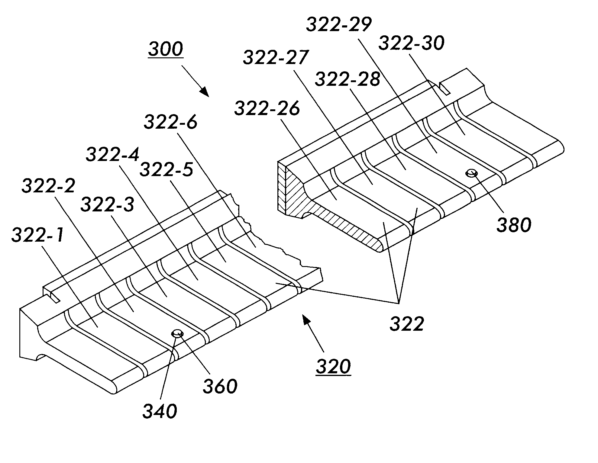
This invention relates to transducers that are tuned to resonate such that a velocity uniformity deviation of the transducers is within a specified limit, and to methods and systems for tuning such transducers. In various exemplary embodiments of the systems, methods and transducers of this invention, mass is added to one or more transducer waveguide segments that are causing large velocity uniformity deviations. In other exemplary embodiments of the systems, methods and transducers of this invention, mass is subtracted from one or more transducer waveguide segments that are causing large velocity uniformity deviations. In still other exemplary embodiments, mass is added to at least one waveguide segment and mass is subtracted from at least one other waveguide segment.

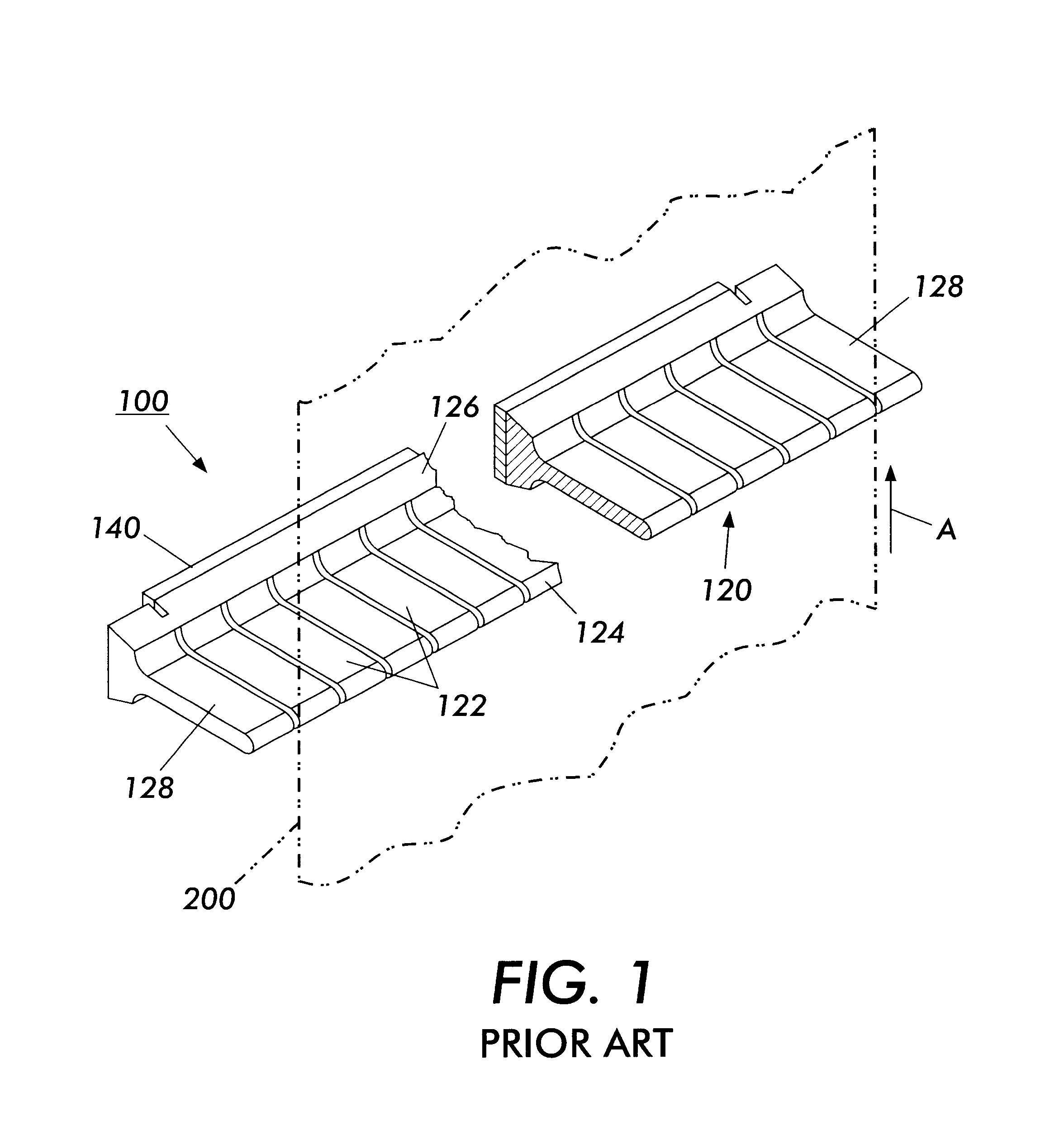
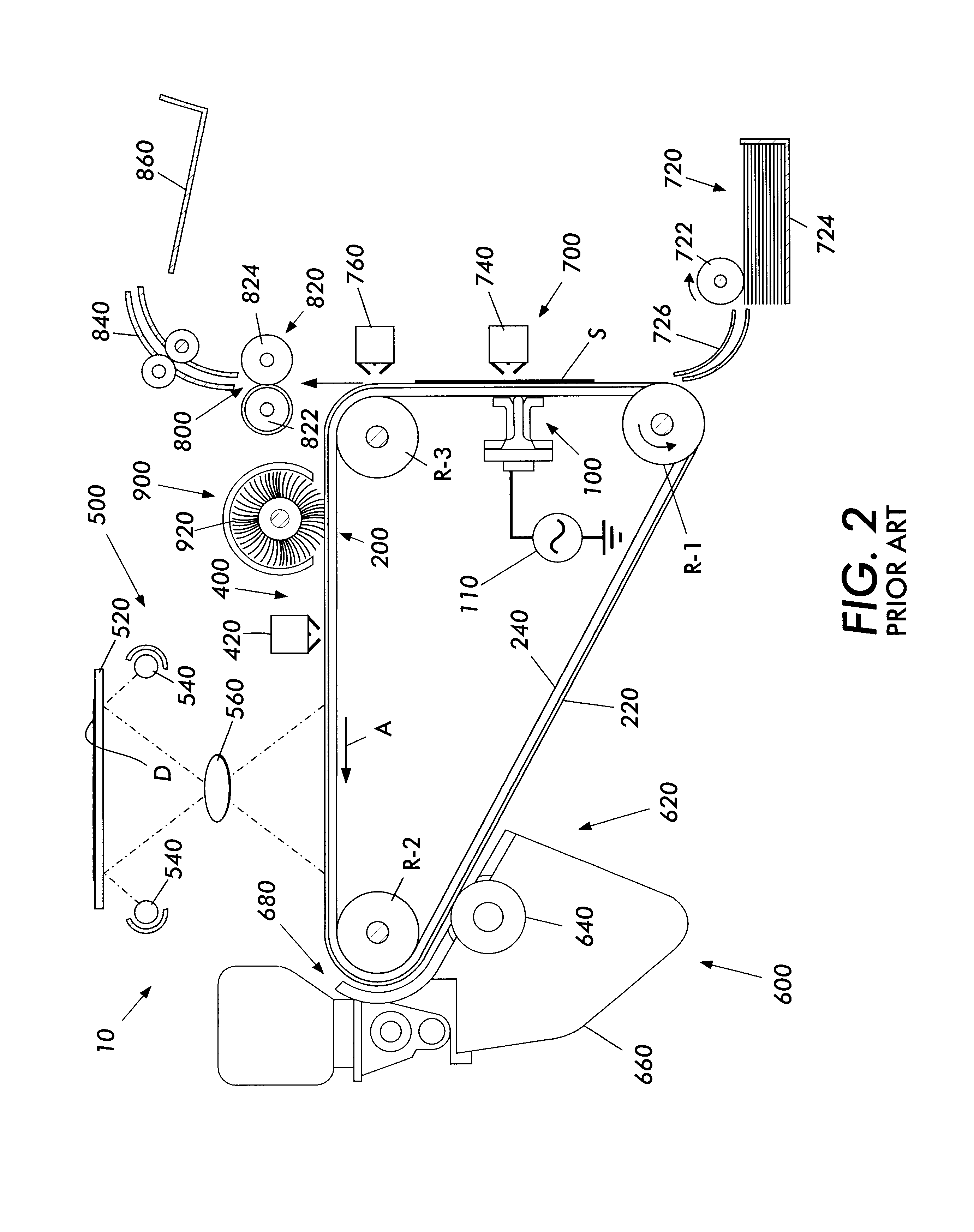
FIG. 1 shows an example of a conventional transducer 100. This transducer is described more fully in U.S. Pat. No. 5,515,148, incorporated herein by reference in its entirety.

The transducer 100 includes a vibratory ene...


PUM


Abstract

A transducer includes a vibratory energy producing element that generates vibratory energy and a waveguide member coupled to the vibratory energy producing element and transmitting the vibratory energy. The waveguide member has a longitudinal axis and is divided along the longitudinal axis into a plurality of waveguide segments. The transducer is tuned, i.e., brought into specification, by altering a mass of at least one of the waveguide segments relative to a mass of the other waveguide elements.

Description

1. Field of InventionThis invention relates to methods and systems for tuning a transducer, and to transducers produced by such methods and systems.2. Description of Related ArtIn a typical electrophotographic printing process, a photoconductive member is initially charged to a substantially uniform potential and the charged portion of the photoconductive member is exposed to a light image of an original document being reproduced. Exposing the charged photoconductive member selectively dissipates the charge on the photoconductive member in the irradiated areas. Thus, an electrostatic latent image can be recorded on the photoconductive member corresponding to informational areas contained within the original document used to expose the photoconductive member. After the electrostatic latent image is recorded on the photoconductive member, the latent image is developed by bringing a developer material into contact with the photoconductive member. Generally, the developer material is ma...

Claims


Application Information

Patent Timeline
IPC IPC(8): B06B3/00G03G15/16B06B1/06
CPCB06B3/00G03G15/16
Inventor MONTFORT, DAVID B.FALVO, JOHN R.
Owner XEROX CORP
Why Eureka
Try Eureka