Network switch providing dynamic load balancing

a network switch and dynamic load technology, applied in data switching networks, digital transmission, time-division multiplexing selection, etc., can solve problems such as labor-intensive manual load balancing, system throughput not optimal, and ineffective manual load balancing

Inactive Publication Date: 2001-03-27
RPX CORP
View PDF3 Cites 87 Cited by
  • Summary
  • Abstract
  • Description
  • Claims
  • Application Information

AI Technical Summary

Problems solved by technology

But load balancing has been problematic.
But if the traffic to some network addresses is much higher than the traffic to others, the load will riot be balanced and system throughput will not be optimal.
However such manual load balancing is labor intensive and often ineffective when good traffic data is not available or when there are frequent changes in the amount of traffic to particular network addresses.

Method used


Image

  • Network switch providing dynamic load balancing
  • Network switch providing dynamic load balancing
  • Network switch providing dynamic load balancing

Examples


Embodiment Construction

)

Network Topology

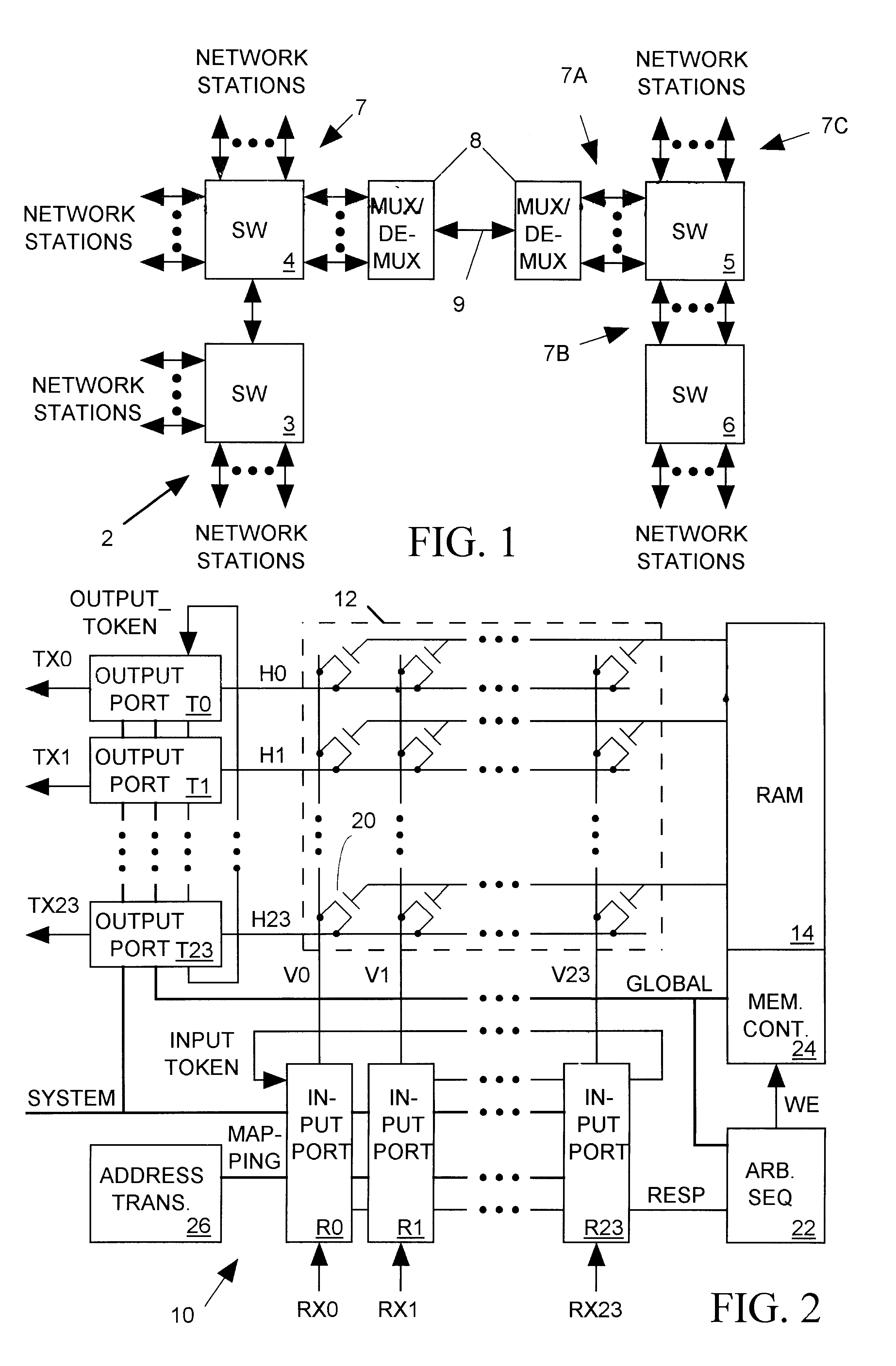
FIG. 1 illustrates a computer network 2 employing a set of network switches 3-6 to route data packets between various network stations. Each network switch 3-6 includes a set of input / output ports 7, each input / output port linking the network switch to one or more network stations or to an input / output port 7 of another network switch. When a network station wants to send data to another network station, it forwards the data to an input port of one of network switches 3-6. If the destination station is connected to an output port of the receiving network switch, the receiving switch forwards the packet directly to the destination station. On the other hand, when the destination station is connected to another switch, the switch receiving the packet forwards the packet to that other network switch possibly via an intervening network switch.

Network 2 can be easily expanded by connecting additional switches to the system. There are various alternative arrangements for ...


PUM


Abstract

A network switch routes data transmissions between network stations, each data transmission including network addresses of the source and destination network stations. The network switch includes a set of input/output (I/O) ports each for receiving data transmissions from and transmitting data transmissions to a subset of the network stations. Each I/O port is identified by a "physical" port ID and a "logical" port ID. While each I/O port's physical port ID is unique, all I/O ports that can route data to the same subset of network stations share the same logical port ID. Each I/O port receiving a data transmission from a network station sends its logical port ID and the network addresses included in the data transmission to an address translation system. The address translation system uses data in the translation request to maintain a lookup table relating each subset of network addresses to a logical port ID identifying all I/O ports that communicate with network stations identified by that subset of network address. The address translation system responds to an address translation request by returning the logical port ID of all I/O ports that can send data transmissions to a destination station identified by the destination address included in the data transmission. In response to the returned logical port ID, the network switch establishes a data path for the data transmission from the I/O port receiving the data transmission and any idle I/O port having that logical port ID.

Description

1. Field of the InventionThe present invention relates in general to a network switch for routing network data transmissions between network stations, and in particular to a switch including a system for dynamically balancing loads over multiple output ports servicing the same set of network stations.2. Description of Related ArtNetworks transfer data between computers or other types of network stations. For example 10BASE-T Ethernet systems use sets of twisted pair conductors to connect network stations to a central hub or switch. A network switch includes input ports for receiving data packets from various network sources, output ports for forwarding packets to various network destinations and a switching mechanism such as a crosspoint switch for selectively routing each incoming packet from an input port to the appropriate output port. The network switch also includes an address translation system which relates a network destination address included in each incoming packet to an ...

Claims


Application Information

Patent Timeline
Patent Type & Authority Patents(United States)
IPC IPC(8): H04Q11/04H04L12/56H04L12/70H04L12/803
CPCH04L47/125H04Q11/0478H04L2012/562H04L2012/568
Inventor PANNELL, DONALD ROBERTHEMMING, ROBERT DONALD
Owner RPX CORP
Why Eureka
Try Eureka